Sign In
Upload
Manuals
Brands
Hypertherm Manuals
Chiller
NVI-5001-CE-MC-M
Hypertherm NVI-5001-CE-MC-M Manuals
Manuals and User Guides for Hypertherm NVI-5001-CE-MC-M. We have
1
Hypertherm NVI-5001-CE-MC-M manual available for free PDF download: User Manual
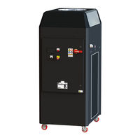
Hypertherm NVI-5001-CE-MC-M User Manual (77 pages)
Plasma Cutter Chiller
Brand:
Hypertherm
| Category:
Chiller
| Size: 8 MB
Table of Contents
Table of Contents
3
1 Specifications
8
Table 1: Chiller Specifications
8
2 Important Safety Instructions
9
3 Machine Label Definitions
10
Table 2: Machine Label Definitions
10
4 Introduction
11
Rated Capacity
12
Figure 1: Plasma Cutter Chiller (Electrical Enclosure Side)
12
Table 3: Koolant Koolers Plasma Cutter Chiller Model Information
12
Figure 2: Plasma Cutter Chiller (Plumbing I/O Side)
13
5 Site Planning
14
Overall Dimensions
14
Location Considerations
14
Environmental Requirements
14
Figure 3: Chiller Overall Dimensions
14
Table 4: Chiller Operating Environmental Requirements
14
Elevation
15
Electrical Enclosure Clearance
15
Service Door Clearance
15
Air Intake and Exhaust Clearance
16
Figure 4: Chiller Air Intake and Discharge Clearances
16
Proximity to the Plasma Cutting System
17
6 Installation
17
Checking for Shipping Damage
17
Transportation
17
Unpacking from the Crate
18
Figure 5: Crated Chiller
18
Internal Access
19
From the Air Intake/Filter Side
19
From the Door Side
19
Electrical Supply Mains
20
Mains Power Requirements
20
Figure 6: Chiller Internal Access
20
Table 5: Chiller Electrical Supply Power Requirements
20
Mains Connectivity
21
Figure 7: Chiller Electrical Enclosure Side
22
Figure 8: Electrical Enclosure Bottom View (Inside Chiller)
22
Figure 9: Electrical Panel (Simplified)
23
Interlock Connections
24
Ethernet Connection
24
Plumbing Connections
24
Table 6: Chiller Plumbing Connections
24
Coolant Reservoir Filling
25
Figure 10: Chiller Plumbing & Electrical Connectivity
25
Refrigerant Filling
26
Installation Checklist
26
7 Operation
27
Pre-Startup
27
Power-Up
27
Fault Check
27
Setting the Line Power Frequency
27
Compressor Warm-Up
27
Initial Startup
28
Local Mode Start-Up
28
Table 7: Recommended Compressor Warm-Up Time
28
Hypertherm, Inc. Part Number
28
Remote Mode
29
Shutdown
29
Service
30
8 Controller
31
Navigation
31
Figure 11: Chiller's Controller
31
Alarms
32
Turning off the Buzzer
32
Viewing Active Alarms
32
Resetting Alarms
32
Main Menu
33
Chiller Status
33
Figure 12: Controller Main Menu
33
Table 8: Chiller Statuses
33
Monitoring
35
Figure 13: Monitoring, Temperatures
35
Figure 14: Monitoring, System Status
35
Figure 15: Monitoring, Condenser & Suction Data
35
Figure 16: Monitoring, Process Fluid Circuit
36
Figure 17: Monitoring, Recirculation Circuit
36
Figure 18: Monitoring, Filter Status
36
Figure 19: Monitoring, Ambient Temperature
37
Devices
38
Figure 20: Devices
38
Figure 21: Devices, Compressor Status
38
Figure 22: Devices, Process Pump Status
38
Figure 23: Devices, Recirculation Pump Status
39
Figure 24: Devices, Heater Status
39
Figure 25: Devices, Fan Status
39
Figure 26: Devices, Motorized Hot Gas, LOP Protection
40
Figure 29: Devices, I/O Module
41
Setpoints
42
Figure 30: Setpoints, Temperature
42
Figure 31: Setpoints, Plasma System Outlet Flow
42
Figure 32: Setpoints, Standby Mode
42
Maintenance & Service
43
Figure 33: Maintenance & Service, Main Menu
43
Figure 34: Maintenance & Service, about
43
Figure 35: Maintenance & Service, Contact Service
43
Figure 36: Maintenance & Service, Contact Parts
44
Figure 38: Maintenance & Service, Pump Run Time
44
Figure 40: Maintenance & Service, Alarm Log Export
45
9 Troubleshooting
46
Alarm List
46
Table 9: Alarm List
46
Inline Heater Temperature Limit Switch
50
Refrigeration High Pressure Switch
50
10 Maintenance
51
Suggested Maintenance Checklist
51
Replacing the Particulate Filter Cartridge
52
Figure 41: Chiller Internal Components (Air Filter/Intake Side)
53
Figure 42: Chiller Internal Components (Panel Side)
54
11 Chiller Data Tag
55
Figure 43: Chiller Data Tag
55
12 Factory Contact
56
Service Support Team
56
Parts Department
56
13 Revisions
57
Table 10: Manual Revisions
57
Hypertherm, Inc. Part Number
57
Appendix A (P&I Diagrams)
58
Refrigeration Schematic
58
Plumbing Schematic
59
Appendix B (Electrical Schematics)
60
Plc
61
I/O Module
62
Logic
63
Electrical Panel
64
Electrical BOM
65
Table 11: Electrical Panel Bill of Materials
65
Appendix C (Default Controller Settings)
66
Program Settings
66
Table 12: Default Program Settings
66
Sensor Calibration
67
Table 13: Default Sensor Calibration Settings
67
Alarm Settings
68
Table 14: Default Alarm Settings
68
I/O Module
69
Table 15: I/O Module Default Settings
69
Appendix D (Warranty)
70
Warranty Coverage
70
General Warranty Procedures
71
Warranty Work
71
Warranty Parts
71
Appendix E (Declaration of Conformity)
72
Appendix F (Chiller Registration)
76
Hypertherm, Inc. Part Number
77
Advertisement
Advertisement
Related Products
Hypertherm NVI-5001-NR-CE-MC-M
Hypertherm Koolant Koolers N-Series
Hypertherm Categories
Welding System
Cutter
Flashlight
Industrial Equipment
Controller
More Hypertherm Manuals
Login
Sign In
OR
Sign in with Facebook
Sign in with Google
Upload manual
Upload from disk
Upload from URL