Sign In
Upload
Manuals
Brands
Hydac Manuals
Water Pump
Filtromat OF5 L
Hydac Filtromat OF5 L Manuals
Manuals and User Guides for Hydac Filtromat OF5 L. We have
1
Hydac Filtromat OF5 L manual available for free PDF download: Operating And Maintenance Instructions Manual
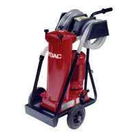
Hydac Filtromat OF5 L Operating And Maintenance Instructions Manual (80 pages)
Brand:
Hydac
| Category:
Water Pump
| Size: 4 MB
Table of Contents
Table of Contents
2
1 General
5
Imprint
5
Documentation Representative
5
Tab. 1 Impressum
5
Tab. 2 Documentation Representative
5
Purpose of this Manual
6
Target Group of the Manual
6
Tab. 3 Target Group
6
Illustrations in the Manual
7
Illustration on the Title Page
7
Fig. 1 Overview / Labeling of the Title Page
7
Representation of Procedural Instructions
8
Representation of Requirements
8
Representation of Intermediate Results/Results
9
Representation of Warning/General Safety Information
10
Signal Words and Their Meaning in the General Safety Information
11
Hazard Symbols / Pictograms
12
Supplementary Symbols
13
Exclusion of Liability/Warranty
14
Notes on Copyright
14
Validity of this Manual
15
2 Safety Information
16
Fire-Fighting / Extinguishing a Fire
17
Fig. 2 Fire Protection Class B
17
Fig. 3 Minimum Distance for Fire Fighting
17
Stoppage in an Emergency (EMERGENCY STOP)
18
Observing Regulatory Information
18
Wear Suitable Clothing
18
3 Overview of the Filtration Unit
19
Proper/Designated Use
20
Improper Use or Use Deviating from Intended Use
21
Checking the Scope of Delivery
22
Fig. 4 Checking the Scope of Delivery
22
Tab. 4 Checking the Scope of Delivery
22
Dimensions
23
OF5 F/L - Dimensions
24
Fig. 5 3389483_Dimensions_01
24
Hydraulic Diagram
25
OF5 F - Hydraulic Diagram
25
Fig. 6 Hydraulic Circuit of the OF5 F
25
OF5 L - Hydraulic Diagram
27
Fig. 7 Hydraulic Circuit of the OF5 L
27
Technical Data
28
Tab. 5 Technical Data
29
Decoding the Name Plate
30
Fig. 8 Decoding the Type Label
30
Tab. 6 Decoding the Type Label
31
Model Code
32
Fig. 9 Model Code OF5 F/L
32
Requirements of the Workplace & Working Environment
33
Components / Operating Elements
34
Fig. 10 OF5 F/L Components/Operating Elements
34
4 Transporting/Storing the Filter Unit
36
Fig. 11 Transporting the OF5 F/L
36
5 Setting up / Assembly / Integration of the Filter Unit
37
Avoiding Siphoning
38
Fig. 12 Avoiding Siphoning
38
Measure or Display Dynamic Pressure / Differential Pressure
39
Fig. 13 Measure or Display Dynamic Pressure / Differential Pressure
39
Avoiding the Mixing of Oils - Emptying the Filter Unit
40
Making the Electrical Connections
41
Connecting the Filter Unit with a Single-Phase Electric Motor
41
Connecting the Filter Unit with a Three-Phase Electric Motor
42
Connecting the Suction/Pressure Port
43
Fig. 14 Pressure Loss Formula
43
Attaching / Connecting the Suction / Pressure Hoses (Accessories)
45
Inserting the Filter Element
46
Commissioning
46
6 Operation
48
Activating the Main Switch
49
Fig. 15 Activate the Main Switch
49
OF5L - Operating Mode
50
Fig. 16 OF5L - Operating Mode Transfer and Filter
50
OF5S - Selecting Operating Modes
51
Operating the Change over Valve
51
Fig. 17 OF5F - Selecting the Operating Modes
51
Observing the Optical Clogging Indicator (Optional)
53
Fig. 18 Observe the Optical Clogging Indicator
53
7 Performing Maintenance
54
Maintenance Table
54
Changing the Filter Element
55
Cleaning the Protective Screen
58
Tab. 7 Suction Lance with Protective Screen
58
8 Decommissioning / Disposal
60
9 Appendix
61
EC Declaration of Conformity
61
Locating Spare Parts
61
Tab. 8 Spare Parts List OF5
62
Tab. 9 Spare Parts List for the OF5F/OF5L
62
Filter Element - Size 330
63
Filter Elements - Size 1300
63
Order Filter Elements
63
Tab. 10 Filter Elements - Size 330
63
Tab. 11 Filter Elements - Size 1300
64
Clogging Indicators - Technical Data
65
Differential Pressure Indicator, Visual - VM X B.X
65
Fig. 19: Differential Pressure Indicator - Visual VM X B.X
65
Tab. 12: Differential Pressure Indicator -Visual VM X B.X
66
Differential Pressure Indicator, Visual - VM X Bm.X
67
Fig. 20: Differential Pressure Gauge, Visual VM X Bm.X
67
Tab. 13: Differential Pressure Indicator, Visual VM X Bm.X
68
Differential Pressure Gauge, Electric (VM X C.X)
69
Fig. 21 Differential Pressure Indicator, Electrical VM X C.X
69
Tab. 14: Differential Pressure Indicator, Electrical VM X C.X
70
Differential Pressure Gauge, Electric (VM X D.X /-L-XX)
71
Fig. 22 Differential Pressure Indicator, Electrical VM X D.X /-Lxx
71
Tab. 15 Differential Pressure Indicator, Electrical VM X D.X / -Lxx
72
Finding a Customer Service Team
73
Tab. 16 Customer Service in Germany
73
Table of Illustrations
74
Glossary
76
Index
77
Advertisement
Advertisement
Related Products
Hydac OLF Compact
Hydac Filtromat OF5 F
Hydac Filtromat OF5F
Hydac Filtromat OF5L
Hydac OFX
Hydac OF5 CM
Hydac Filtromat OF5 C with FCU
Hydac OffLine Filter BiDirectional OLFBD Series
Hydac OFU
Hydac OXiStop OXS-LID/C202
Hydac Categories
Water Filtration Systems
Industrial Equipment
Accessories
Control Unit
Switch
More Hydac Manuals
Login
Sign In
OR
Sign in with Facebook
Sign in with Google
Upload manual
Upload from disk
Upload from URL