Chapters
Table of Contents

Related Manuals for Hydac Filtromat OF5 F

Summary of Contents for Hydac Filtromat OF5 F
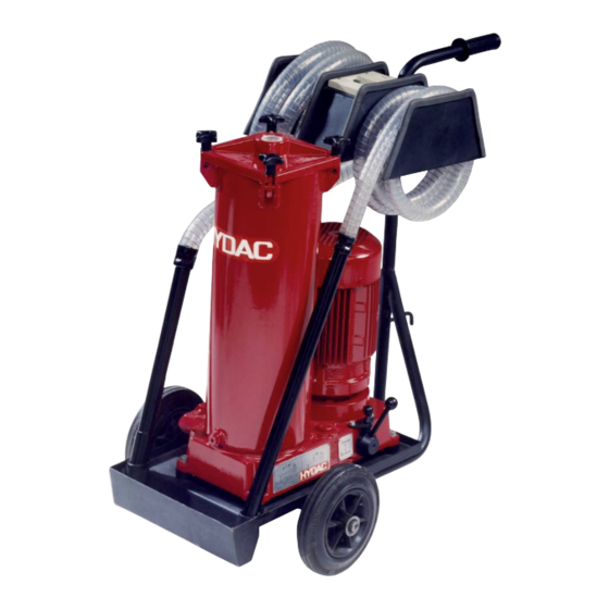
- Page 1 OF5 F / OF5 L Filtromat Operating and Maintenance Instructions English • (translation of original instructions) Document No. : 3160337g • 10/15/2019 Follow these instructions for proper and safe use. Keep for future reference.
-
Page 2: Table Of Contents
Table of Contents HYDAC FILTER SYSTEMS GMBH Table of Contents 1 General ........................ 5 Imprint ...................... 5 Documentation Representative................ 5 Purpose of this manual .................. 6 Target group of the manual................ 6 Illustrations in the manual ................ 7 1.5.1 Illustration on the title page.............. 7 1.5.2... - Page 3 HYDAC FILTER SYSTEMS GMBH Table of Contents 3.5.1 OF5 F - Hydraulic diagram .............. 25 3.5.2 OF5 L - Hydraulic diagram.............. 27 Technical Data .................... 28 Decoding the name plate ................ 30 3.7.1 Model code .................. 32 Requirements of the workplace & working environment ........ 33 Components / Operating elements ..............
- Page 4 Table of Contents HYDAC FILTER SYSTEMS GMBH 8 Decommissioning / Disposal ................... 60 9 Appendix ......................... 61 EC declaration of conformity ................ 61 Locating spare parts.................. 61 9.2.1 Order filter elements ................ 63 9.2.1.1 Filter element - Size 330............ 63 9.2.1.2...
-
Page 5: General
Dipl.Kfm. Wolfgang Haering Tab. 1: Impressum 1.2 Documentation Representative The contact data of the person authorized with the documenta- tion is: Mr. Günter Harge c/o HYDAC International GmbH, Industriegebiet, 66280 Sulzbach / Saar Germany Phone: +49 6897 509 1511 Fax: +49 6897 509 1394 E-mail: guenter.harge@hydac.com... -
Page 6: Purpose Of This Manual
1 | General HYDAC FILTER SYSTEMS GMBH 1.3 Purpose of this manual Before you use this product for the first time or if you have been asked to carry out other work on the product, please read this manual. The use and the handling of the product described in the fol-... -
Page 7: Illustrations In The Manual
HYDAC FILTER SYSTEMS GMBH General | 1 1.5 Illustrations in the manual You will find illustrations in this manual. You can find details re- garding these in the following chapters. 1.5.1 Illustration on the title page You will find the following information on the title page of this... -
Page 8: Representation Of Requirements
1 | General HYDAC FILTER SYSTEMS GMBH The document no. with the index (4) is meant for identifying and reordering the manual. The index is incremented every time the manual is revised or changed. The manual contains a table of contents, a list of tables and figures, an index and a glossary. -
Page 9: Representation Of Intermediate Results/Results
HYDAC FILTER SYSTEMS GMBH General | 1 An example of a procedural instruction with a random se- quence: – Clean the display. – Rinse the product. 1.5.4 Representation of intermediate results/results In the case of some activities, it is necessary to carry out work steps with intermediate results and end results. -
Page 10: Representation Of Warning/General Safety Information
1 | General HYDAC FILTER SYSTEMS GMBH 1.5.5 Representation of warning/general safety information All the warning / general safety information in this manual are highlighted with pictograms and signal words. The pictogram and the signal word give you an indication of the severity of the danger. -
Page 11: Signal Words And Their Meaning In The General Safety Information
HYDAC FILTER SYSTEMS GMBH General | 1 1.5.6 Signal words and their meaning in the general safety information In these instructions you will find the following signal words: DANGER DANGER – The signal word indicates a hazardous situation with a high level of risk, which, if not avoided, will result lethal or serious injury. -
Page 12: Hazard Symbols / Pictograms
1 | General HYDAC FILTER SYSTEMS GMBH 1.6 Hazard symbols / pictograms The following are the safety symbols / pictograms in this man- ual. They indicate specific dangers to persons, property or to the environment. Observe these safety symbols / pictograms and act with particular caution in such cases. -
Page 13: Supplementary Symbols
HYDAC FILTER SYSTEMS GMBH General | 1 Exposed electrical components Danger due to operating pressure Signs used for the required specialist personnel These symbols show the required training/knowledge for in- stallation work and/or maintenance work. Specialist personnel - Electrician Such persons have specific specialist training and several years' work experience. -
Page 14: Exclusion Of Liability/Warranty
Delivery. They are made available to you at the conclusion of the contract at the latest. You will also find these under www.hydac.com -> General Terms and Conditions (T&C). This manual was prepared to the best of our knowledge. Nev- ertheless and despite the greatest care, it cannot be excluded that mistakes could have crept in. -
Page 15: Validity Of This Manual
HYDAC FILTER SYSTEMS GMBH General | 1 1.10 Validity of this manual The diagrams and visualizations in this manual are meant for general illustration purposes. Therefore, representations and functional options can deviate from the delivered product. We reserve the right to changes to the contents of this manual without prior notice. -
Page 16: Safety Information
2 | Safety information HYDAC FILTER SYSTEMS GMBH 2 Safety information DANGER Danger due to unintended use Bodily injury / Damage to property u Never operate the filter unit in potentially explosive atmos- pheres. u The filter unit is to be used only with the permissible oper- ating media. -
Page 17: Fire-Fighting / Extinguishing A Fire
HYDAC FILTER SYSTEMS GMBH Safety information | 2 The General Safety Information provides important information on handling the device. A prerequisite for safe work is the maintenance of all stated General Safety Instructions and pre- cautions. In addition, the local accident prevention specifica- tions and general safety regulations that apply for the area of operation of the device must be observed. -
Page 18: Stoppage In An Emergency (Emergency Stop)
2 | Safety information HYDAC FILTER SYSTEMS GMBH 2.2 Stoppage in an emergency (EMERGENCY STOP) Disconnect the product from all sources of energy in an emer- gency. 2.3 Observing regulatory information Observe the following regulatory information and directives: – Legal and local regulations for accident prevention –... -
Page 19: Overview Of The Filtration Unit
HYDAC FILTER SYSTEMS GMBH Overview of the filtration unit | 3 3 Overview of the filtration unit The OF5 F/L is a filter unit for the offline filtration of hydraulic tanks. In the OF5 S type, it is possible to fill as well as empty a hydraulic tank with an integrated change over valve in addition to the offline filtration. -
Page 20: Proper/Designated Use
3 | Overview of the filtration unit HYDAC FILTER SYSTEMS GMBH 3.1 Proper/designated use Use the filter unit only for the application described in the fol- lowing. The filter unit is used in combination with the permitted filter el- ements (identification -KB) to clean / filter hydraulic and lubri- cating oils in the bypass flow or to fill the hydraulic systems, to transfer as well as drain the hydraulic tanks. -
Page 21: Improper Use Or Use Deviating From Intended Use
3.2 Improper use or use deviating from intended use Any use extending beyond this or deviating therefrom shall not be considered intended use. HYDAC FILTER SYSTEMS GMBH will assume no liability for any damage resulting from such use. This risk is borne solely by the owner. -
Page 22: Checking The Scope Of Delivery
3 | Overview of the filtration unit HYDAC FILTER SYSTEMS GMBH 3.3 Checking the scope of delivery The filter unit is delivered ready for connection without the filter element installed. Before commissioning the unit, check the contents of the package to make sure everything is present. -
Page 23: Dimensions
HYDAC FILTER SYSTEMS GMBH Overview of the filtration unit | 3 3.4 Dimensions Depending on the version, the filter housing/filter unit has dif- ferent dimensions. You can find details regarding these in the following chapters. BeWa OF5F-OF5L 3160337h en-us lq... -
Page 24: Of5 F/L - Dimensions
3 | Overview of the filtration unit HYDAC FILTER SYSTEMS GMBH 3.4.1 OF5 F/L - Dimensions The OF5 F/L filter unit has the following dimensions. Fig. 5: 3389483_Dimensions_01 All dimensions are in mm. 24 / 80 BeWa OF5F-OF5L 3160337h en-us lq... -
Page 25: Hydraulic Diagram
HYDAC FILTER SYSTEMS GMBH Overview of the filtration unit | 3 3.5 Hydraulic diagram The hydraulic diagram of the filter unit varies depending on the version. 3.5.1 OF5 F - Hydraulic diagram The OF5 F filter unit has the following hydraulic diagram. - Page 26 3 | Overview of the filtration unit HYDAC FILTER SYSTEMS GMBH 14 Differential pressure indicator (op- tional) 17 Air bleed screw on the filter housing BLEED 26 / 80 BeWa OF5F-OF5L 3160337h en-us lq...
-
Page 27: Of5 L - Hydraulic Diagram
HYDAC FILTER SYSTEMS GMBH Overview of the filtration unit | 3 3.5.2 OF5 L - Hydraulic diagram The OF5 L filter unit has the following hydraulic diagram. Fig. 7: Hydraulic circuit of the OF5 L 1 Filter housing 3 Drain plug on the filter housing... -
Page 28: Technical Data
3 | Overview of the filtration unit HYDAC FILTER SYSTEMS GMBH 3.6 Technical Data The filter unit has the following technical data: Permissible operating fluid Mineral oils and mineral oil- based raffinates. Permitted operating pres- ≤ 4.5 bar sure Hydraulic connections 1“ according to ISO 228... -
Page 29: Tab. 5 Technical Data
HYDAC FILTER SYSTEMS GMBH Overview of the filtration unit | 3 Storage duration unlimited Replace all the seals before commissioning after a storage duration of ≥ 2 years. Electrical power consump- OF5x10x3 ≈ 0.75 kW@50Hz tion OF5x10x4 ≈ 1.5 kW@50Hz OF5x10x6 Degree of protection... -
Page 30: Decoding The Name Plate
3.7 Decoding the name plate Identification details of the filter unit can be found on the name plates on the filter unit and the components. Always mention the part no. and the serial no. when contacting HYDAC. Fig. 8: Decoding the type label Item Description ->... -
Page 31: Tab. 6 Decoding The Type Label
HYDAC FILTER SYSTEMS GMBH Overview of the filtration unit | 3 Item Description Pressure max. -> Operating pressure, maximum Weight -> Empty weight Flow rate -> Flow rate Temp. Oil -> Permissible oil temperature range Temp. Amb. -> Permitted ambient temperature range Volume ->... -
Page 32: Model Code
3 | Overview of the filtration unit HYDAC FILTER SYSTEMS GMBH 3.7.1 Model code The filter unit is defined by the following model code: OF5 F 10 P 6 N 1 B 05 E / - Basic Type Types = with change over... -
Page 33: Requirements Of The Workplace & Working Environment
HYDAC FILTER SYSTEMS GMBH Overview of the filtration unit | 3 3.8 Requirements of the workplace & working environment Requirements of the workplace as well as the working environ- ment can be found in the chapter "Technical data" under: – Permitted ambient temperature range –... -
Page 34: Components / Operating Elements
3 | Overview of the filtration unit HYDAC FILTER SYSTEMS GMBH 3.9 Components / Operating elements The filter unit has the following components/operating ele- ments: Fig. 10: OF5 F/L components/operating elements 34 / 80 BeWa OF5F-OF5L 3160337h en-us lq... - Page 35 HYDAC FILTER SYSTEMS GMBH Overview of the filtration unit | 3 Item Tool Filter housing Filter cover Drain plug on the filter housing DRAIN Suction hose with lance and suction strainer Pressure hose with lance Floor plate with drip tray...
-
Page 36: Transporting/Storing The Filter Unit
4 | Transporting/storing the filter unit HYDAC FILTER SYSTEMS GMBH 4 Transporting/storing the filter unit Fully empty the filter unit before transporting it or putting it into storage. Remove the used filter element and dispose of it in an environmentally friendly manner. Clean the inside of the filter housing. -
Page 37: Setting Up / Assembly / Integration Of The Filter Unit
HYDAC FILTER SYSTEMS GMBH Setting up / assembly / integration of the filter unit | 5 5 Setting up / assembly / integration of the filter unit Observe the following notices for mounting the filter unit. – Place the filter unit horizontally on a stable, even and hori- zontal surface. -
Page 38: Avoiding Siphoning
5 | Setting up / assembly / integration of the filter unit HYDAC FILTER SYSTEMS GMBH 5.1 Avoiding siphoning If there is a height difference (ΔH) between the suction side and pressure side container/system, the lower line can develop a suction effect and trigger the siphoning effect between the communicating containers/systems. -
Page 39: Measure Or Display Dynamic Pressure / Differential Pressure
HYDAC FILTER SYSTEMS GMBH Setting up / assembly / integration of the filter unit | 5 5.2 Measure or display dynamic pressure / differential pressure If pressure is measured in a hydraulic system, the type of mea- surement such as dynamic pressure or differential pressure as well as the measurement point is critical, as shown in the following diagram. -
Page 40: Avoiding The Mixing Of Oils - Emptying The Filter Unit
5 | Setting up / assembly / integration of the filter unit HYDAC FILTER SYSTEMS GMBH 5.3 Avoiding the mixing of oils - Emptying the filter unit If you want to use the same oil for operation as in the previous operation, it is not serious if the oils are mixed. -
Page 41: Making The Electrical Connections
HYDAC FILTER SYSTEMS GMBH Setting up / assembly / integration of the filter unit | 5 5.4 Making the electrical connections Depending on the version, the filter unit has different drive mo- tors (different voltage / output / number of phases, etc.). Follow the instructions in the next section to electrically connect the fil- ter unit. -
Page 42: Connecting The Filter Unit With A Three-Phase Electric Motor
5 | Setting up / assembly / integration of the filter unit HYDAC FILTER SYSTEMS GMBH 5.4.2 Connecting the filter unit with a three-phase electric motor The filter unit is equipped with a three-phase electric motor, on/ off switch, motor protection and connection plug; connect the filter unit in accordance with the following steps. -
Page 43: Connecting The Suction/Pressure Port
HYDAC FILTER SYSTEMS GMBH Setting up / assembly / integration of the filter unit | 5 5.5 Connecting the suction/pressure port Take into account the pressure loss when connecting suction/ pressure hoses. The suction / pressure hoses from the filter unit Accessories list are matched to the filter unit. - Page 44 5 | Setting up / assembly / integration of the filter unit HYDAC FILTER SYSTEMS GMBH – Note that the nominal size of the connected hose/piping must correspond to the cross-section of the connection thread. – Make sure that the connection hoses/piping (suction side/ pressure side) do not cause any tension or vibrations to be carried over to the filter unit.
-
Page 45: Attaching / Connecting The Suction / Pressure Hoses (Accessories)
HYDAC FILTER SYSTEMS GMBH Setting up / assembly / integration of the filter unit | 5 5.6 Attaching / connecting the suction / pressure hoses (Accessories) Take into account the pressure loss when connecting suction/ pressure hoses. The suction / pressure hoses from the filter unit Accessories list are matched to the filter unit. -
Page 46: Inserting The Filter Element
5 | Setting up / assembly / integration of the filter unit HYDAC FILTER SYSTEMS GMBH 5.7 Inserting the filter element The filter unit has no filter element installed upon delivery from the factory. Before commissioning check whether a filter ele- ment is present in the filter housing. - Page 47 HYDAC FILTER SYSTEMS GMBH Setting up / assembly / integration of the filter unit | 5 1. Switch the filter unit on and monitor the suction perfor- mance. ð If the filter unit is not pumping any fluid after a maxi-...
-
Page 48: Operation
6 | Operation HYDAC FILTER SYSTEMS GMBH 6 Operation Different operating modes are available depending on the ver- sion (see the model code) of the filter unit. The filter unit is equipped with a clogging indicator (differential pressure gauge or dynamic pressure indicator) in the filter bowl cover to monitor the service life of the filter element. -
Page 49: Activating The Main Switch
HYDAC FILTER SYSTEMS GMBH Operation | 6 6.1 Activating the main switch Depending on the version with a visual or electrical clogging in- dicator, the main switch differs according to the following fig- ure: Fig. 15: Activate the main switch L Main switch / E-STOP... -
Page 50: Of5L - Operating Mode
6 | Operation HYDAC FILTER SYSTEMS GMBH 6.2 OF5L – Operating mode The OF5L filter unit cannot change over between the operating modes. This filter unit can only be operated in the operation mode - Transfer with filtration. Fig. 16: OF5L - Operating mode Transfer and filter... -
Page 51: Of5S - Selecting Operating Modes
HYDAC FILTER SYSTEMS GMBH Operation | 6 6.3 OF5S - Selecting operating modes The OF5F filter unit has a change over valve for changing over the operating modes. See chapter Operating the change over valve [} 51] for changing the operating modes over. - Page 52 6 | Operation HYDAC FILTER SYSTEMS GMBH NOTICE Switching valve in an intermediate position An intermediate position causes a mixed function u Press the change over valve up to its end position and in the centre position until the locking pins (6) engage audibly and visibly.
-
Page 53: Observing The Optical Clogging Indicator (Optional)
HYDAC FILTER SYSTEMS GMBH Operation | 6 6.4 Observing the optical clogging indicator (optional) If the filter unit / filter housing is equipped with an optical clog- ging indicator, then check it daily. Change the filter element at a permissible differential pressure across the filter element or once the clogging indicator enters the red zone. -
Page 54: Performing Maintenance
7 | Performing maintenance HYDAC FILTER SYSTEMS GMBH 7 Performing maintenance 7.1 Maintenance table Additional information Operation Changing the fil- ter element Changing the fil- ter element Cleaning the pro- tective screen Cleaning the pro- tective screen 1 - Operating personnel... -
Page 55: Changing The Filter Element
HYDAC FILTER SYSTEMS GMBH Performing maintenance | 7 7.2 Changing the filter element In this chapter, you will find the procedure for changing the fil- ter element. 1x Allen wrench = 5 mm Suitable receiver bin for collecting the oil from the filter housing. - Page 56 7 | Performing maintenance HYDAC FILTER SYSTEMS GMBH 5. Lift the filter cover up and remove the filter element. Dispose the filter element in an environmentally safe manner. 6. Clean the - inside of the filter bowl of any course dirt - the sealing surfaces on the filter bowl and filter cover.
- Page 57 HYDAC FILTER SYSTEMS GMBH Performing maintenance | 7 10. Fit the filter cover. NOTICE! Pay attention to the O-ring in filter cover while doing so. It must not be damaged. 11. Fold the four star gripped screws upwards and turn the star gripped nuts clockwise, screw them crosswise uni- formly.
-
Page 58: Cleaning The Protective Screen
7 | Performing maintenance HYDAC FILTER SYSTEMS GMBH 7.3 Cleaning the protective screen To protect the pump from coarse contaminant particles or for- eign bodies, a protective screen is installed in the suction lance. Clean the strainer regularly. Check the protective screen immediately in the event of insufficient suction or delivery ac- tion. - Page 59 HYDAC FILTER SYSTEMS GMBH Performing maintenance | 7 1. Rotate the protection pipe (5) away from the suction lance (2) in counterclockwise direction. 2. Remove the protective screen (4) from the protection pipe. 3. Clean the protective screen (4) by washing it out and then blowing it out with compressed air.
-
Page 60: Decommissioning / Disposal
8 | Decommissioning / Disposal HYDAC FILTER SYSTEMS GMBH 8 Decommissioning / Disposal – Empty the product completely, including all of its compo- nents, before decommissioning. Disconnect or remove the electric, pneumatic or hydraulic connections. – Dispose of the packaging material in an environmentally friendly manner. -
Page 61: Appendix
HYDAC FILTER SYSTEMS GMBH Appendix | 9 9 Appendix In this annex, you will find supplementary information on the product. 9.1 EC declaration of conformity The ED declaration of conformity can be found in the Technical Documentation that is part of the scope of delivery for the product. -
Page 62: Tab. 8 Spare Parts List Of5
9 | Appendix HYDAC FILTER SYSTEMS GMBH Description Part no. Differential pressure indicator FKM 316556 Tab. 8: Spare parts list OF5… *) available on request Description Part no. Pressure hose with lance, length = NW25 381465 3 m Pressure hose with lance, length =... -
Page 63: Order Filter Elements
HYDAC FILTER SYSTEMS GMBH Appendix | 9 9.2.1 Order filter elements Select the filter element depending on size of your filter unit. In the following you can find the filter elements as per size, filter unit and sealing material. 9.2.1.1 Filter element - Size 330... -
Page 64: Tab. 11 Filter Elements - Size 1300
9 | Appendix HYDAC FILTER SYSTEMS GMBH Description Part no. Filter element 10 µm 1300 R 010 ON/-V- FPM 1263762 Filter element 20 µm 1300 R 020 ON/-KB NBR 1263062 Filter element 20 µm 1300 R 020 ON/-V- FPM 1263763 Filter element 40 µm 1300 R 040 AM/-KB NBR 1267699 Tab. 11: Filter elements - size 1300... -
Page 65: Clogging Indicators - Technical Data
HYDAC FILTER SYSTEMS GMBH Appendix | 9 9.3 Clogging indicators - technical data Listed below are the technical data pertaining to the optional, optical or electrical clogging indicators suitable for the installa- tion in the filter housing / filter unit. -
Page 66: Tab. 12: Differential Pressure Indicator -Visual Vm X B.x
9 | Appendix HYDAC FILTER SYSTEMS GMBH Permissible operating over- ≤ 210 bar pressure Permitted temperature range -30 … +100°C Connector threads G ½ Installation space required According to HN 28-22 Maximum tightening torque 33 Nm Tab. 12: Differential pressure indicator -visual VM x B.x 66 / 80 BeWa OF5F-OF5L 3160337h en-us lq... -
Page 67: Differential Pressure Indicator, Visual - Vm X Bm.x
HYDAC FILTER SYSTEMS GMBH Appendix | 9 9.3.2 Differential pressure indicator, visual – VM x BM.x The optical differential pressure gauge reacts to the increasing pressure difference at the increasing contamination level of the filter element. Fig. 20: Differential pressure gauge, visual VM x BM.x... -
Page 68: Tab. 13: Differential Pressure Indicator, Visual Vm X Bm.x
9 | Appendix HYDAC FILTER SYSTEMS GMBH Permissible operating over- ≤ 210 bar pressure Permitted temperature range -30 … +100°C Connector threads G ½ Installation space required According to HN 28-22 Tab. 13: Differential pressure indicator, visual VM x BM.x 68 / 80 BeWa OF5F-OF5L 3160337h en-us lq... -
Page 69: Differential Pressure Gauge, Electric (Vm X C.x)
HYDAC FILTER SYSTEMS GMBH Appendix | 9 9.3.3 Differential pressure gauge, electric (VM x C.x) The electric clogging indicator reacts to the increasing pres- sure difference at the increasing contamination level of the fil- ter element. Fig. 21: Differential pressure indicator, electrical VM x C.x... -
Page 70: Tab. 14: Differential Pressure Indicator, Electrical Vm X C.x
9 | Appendix HYDAC FILTER SYSTEMS GMBH Response pressure and indi- VM 2 C.x = 2 bar -10% cation range respectively VM 3 C.x = 3 bar -10% VM 5 C.x = 5 bar -10% Permissible operating over- ≤ 210 bar pressure Permitted temperature range -30 … +100°C Connector threads G ½ Installation space required According to HN 28-22 Maximum tightening torque 33 Nm... -
Page 71: Differential Pressure Gauge, Electric (Vm X D.x /-L-Xx)
HYDAC FILTER SYSTEMS GMBH Appendix | 9 9.3.4 Differential pressure gauge, electric (VM x D.x /-L- The electric clogging indicator reacts to the increasing pres- sure difference at the increasing contamination level of the fil- ter element. Fig. 22: Differential pressure indicator, electrical VM x D.x /-Lxx... -
Page 72: Tab. 15 Differential Pressure Indicator, Electrical Vm X D.x / -Lxx
9 | Appendix HYDAC FILTER SYSTEMS GMBH Response pressure and indi- VM 2 D.x = 2 bar -10% cation range respectively VM 3 D.x = 3 bar -10% VM 5 D.x = 5 bar -10% Permissible operating over- ≤ 210 bar pressure Permitted temperature range -30 … +100°C Connector threads G ½ Installation space required According to HN 28-22 Maximum tightening torque 33 Nm... -
Page 73: Finding A Customer Service Team
HYDAC SYSTEMS & SERVICES GMBH Friedrichsthaler Str. 15, Werk 13 66450 Neunkirchen - Heinitz Germany... - Page 74 Table of Illustrations HYDAC FILTER SYSTEMS GMBH Table of Illustrations Fig. 1 Overview / labeling of the title page ............Fig. 2 Fire protection class B ................Fig. 3 Minimum distance for fire fighting............. Fig. 4 Checking the scope of delivery ..............
- Page 75 HYDAC FILTER SYSTEMS GMBH Index of Tables Index of Tables Tab. 1 Impressum....................Tab. 2 Documentation Representative ..............Tab. 3 Target group ..................... Tab. 4 Checking the scope of delivery ..............Tab. 5 Technical Data ..................Tab. 6 Decoding the type label ................
-
Page 76: Glossary
The General Terms and Conditions are available at our home page www.hydac.com -> General Terms and Conditions. HN 28-22 HYDAC standard 28-22 with dimen- sions for the installation space for clogging indicators. KB marking of filter elements Filter elements with the -KB mark- ing do not have a bypass. -
Page 77: Index
HYDAC FILTER SYSTEMS GMBH Index Index Branches 73 Hotline 73 calculating pressure loss 43 Imprint 5 Clogging indicator Differential pressure indicator 66, 68, 70, 72 main switch Commissioning 46 EMERGENCY-STOP 49 manufacturer 5 decommissioning 60 Differential pressure indicator, electrical operation mode VM x C.x... - Page 78 Index HYDAC FILTER SYSTEMS GMBH warranty 14 78 / 80 BeWa OF5F-OF5L 3160337h en-us lq...
Need help?
Do you have a question about the Filtromat OF5 F and is the answer not in the manual?
Questions and answers