Sign In
Upload
Manuals
Brands
Huahuan Electronics Manuals
Network Hardware
HT8000-I
Huahuan Electronics HT8000-I System Manuals
Manuals and User Guides for Huahuan Electronics HT8000-I System. We have
1
Huahuan Electronics HT8000-I System manual available for free PDF download: User Manual
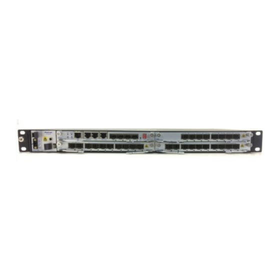
Huahuan Electronics HT8000-I User Manual (119 pages)
Multi-service OTN/WDM Transport Platform
Brand:
Huahuan Electronics
| Category:
Network Hardware
| Size: 2 MB
Table of Contents
Table of Contents
5
Contents
7
List of Figures
8
1 Overview
14
Introduction
14
Typical Application
15
Metropolitan Broadband Bearing
15
Figure 1-1 Metropolitan Broadband Bearing Diagram
16
Leased Line Service
17
Figure 1-2 Leased Line Models
17
Figure 1-3 Private Line Networking Diagram
18
2 Hardware Architecture
19
Device Configuration
19
Figure 2-1 Slot Layout of HT8000-I
19
Table 2-1 Card Configuration List of HT8000-I
19
Figure 2-2 Slot Layout of HT8000- II
24
Table 2-2 Card Configuration List of HT8000- II
24
Figure 2-3 Slot Layout of HT8000- VI
29
Table 2-3 Card Configuration List of HT8000-VI
29
Card Introduction
33
DC Power-Supply Card/700W (FPS7-D48)
33
Figure 2-4 the Front Panel Diagram of FPS7-D48
33
DC Power-Supply Card/100W (FPS1-D48)
34
Table 2-4 LED Functional Descriptions of FPS7-D48
34
Table 2-5 Description of Power Interface
34
AC Power-Supply Card (FPS1-A220)
35
Figure 2-5 the Front Panel Diagram of FPS1-D48
35
Table 2-6 LED Functional Descriptions of FPS1-D48
35
Table 2-7 Description of Power Interface
35
4-Channel OSC Card (FS4)
36
Figure 2-6 the Front Panel Diagram of FPS1-A220
36
Figure 2-7 the Front Panel Diagram of FS4
36
Table 2-8 LED Functional Descriptions of FPS1-A220
36
Management Clock Card (MC01)
37
Table 2-9 LED Functional Descriptions of FS4
37
Figure 2-8 the Front Panel Diagram of MC01
38
Table 2-10 LED Functional Descriptions of MC01
38
Table 2-11 Dip Switch Functions
39
Table 2-12 Marks and Definitions of Management Ports
39
Figure 2-9 Pin Definition of RJ45 Connector
40
Table 2-13 RJ-45 Ethernet Socket Definition
40
Table 2-14 RJ45 Socket Definition of CONSOLE Management Port
40
Table 2-15 Definition of External Clock Input\Output Ports
41
Table 2-16 1Pps+Tod Port Pin Definition
41
Expandable Chassis Cascade Card (MC02)
42
Figure 2-10 Reset Button
42
Figure 2-11 the Front Panel Diagram of MC02
42
Anyrate+2 OTU Muxponder Card (O2A8-D)
43
Figure 2-12 Reset Button
43
Figure 2-13 the Front Panel Diagram of O2A8-D
43
4-Channel Transponder Card (O4M4)
44
Figure 2-14 the Front Panel Diagram of O4M4
44
Table 2-17 LED Functional Descriptions of O2A8-D
44
2-Channel Transponder Card (O2M2-P)
45
Figure 2-15 the Front Panel Diagram of O2M2-P
45
Table 2-18 LED Functional Descriptions of O4M4
45
16-Channel DWDM MUX/DEMUX Card (D1GH-S-LD2136)
46
Figure 2-16 the Front Panel Diagram of D1GH-S-LD2136
46
Table 2-19 LED Functional Descriptions of O2M2-P
46
Table 2-20 LED Functional Descriptions of D1GH-S-LD2136
46
8-Channel DWDM MUX/DEMUX Card (D1G8-SE-LD2128/D1G8-SE-LD2936/D1G8-SE-LD3744/D1G8-SE-LD4552/D1G8-S E-LD5360)
47
Figure 2-17 the Front Panel Diagram of D1G8-SE-LD2128/ D1G8-SE-LD2936/D1G8-SE-LD3744/D1G8-SE-LD4552/D1G8-SE-LD5360
47
Table 2-21 LED Functional Descriptions of D1G8-SE-LD2128/ D1G8-SE-LD2936/D1G8-SE-LD3744/D1G8-SE-LD4552/D1G8-SE-LD5360
48
12-Channel DWDM MUX/DEMUX Card (D1GD-S-LD2132/D1GD-S-LD3344/D1GD-S-LD4556)
49
Figure 2-18 the Front Panel Diagrams of D1GD-S-LD2132/D1GD-S-LD3344/D1GD-S-LD4556
49
40-Channel DWDM MUX Card (D1MF-S-LD2160)
50
Figure 2-19 the Front Panel Diagram of D1MF-S-LD2160
50
Table 2-22 LED Functional Descriptions of D1GD-S-LD2132/D1GD-S-LD3344/D1GD-S-LD4556
50
40-Channel DWDM DEMUX Card (D1DF-S-LD2160)
51
Figure 2-20 the Front Panel Diagram of D1DF-S-LD2160
51
Table 2-23 LED Functional Descriptions of D1MF-S-LD2160
51
8-Channel CWDM MUX/DEMUX Card (C1G8-S-LC4761)
52
Figure 2-21 the Front Panel Diagram of C1G8-S-LC4761
52
Table 2-24 LED Functional Descriptions of D1DF-S-LD2160
52
10-Channel CWDM MUX/DEMUX Card (C1GX-LC4361)
53
Figure 2-22 the Front Panel Diagram of C1GX-LC4361
53
Table 2-25 LED Functional Descriptions of C1G8-S-LC4761
53
2-Channel, Single-Fiber, 2-Way MUX/DEMUX Card(C1G2-BSE-LC5157
54
Figure 2-23 the Front Panel Diagram of C1G2-BSE-LC5157
54
Table 2-26 LED Functional Descriptions of C1GX-LC4361
54
2-Way, Single CH CWDM Card (C2G1-E-LC51)
55
Table 2-27 LED Functional Descriptions of C1G2-BSE-LC5157
55
3-Channel, Single-Fiber, 2-Way CWDM MUX/DEMUX Card (C1G3-BSE-LC2737/ C1G3-BSE-LC3727)
56
Figure 2-24 the Front Panel Diagram of C2G1-E-LC51
56
Table 2-28 LED Functional Descriptions of C2G1-E-LC51
56
C-Band, Pre+Boost EDFA (A2GC-SM-P21.P17/ A2GC-SM-P17.P12)
57
Figure 2-25 the Front Panel Diagrams of C1G3-BSE-LC2737/ C1G3-BSE-LC3727
57
Figure 2-26 the Front Panel Diagrams of A2GC-SM-P21.P17/A2GC-SM-P17.P12
58
Table 2-29 LED Functional Descriptions of A2GC-SM-P21.P17/A2GC-SM-P17.P12
58
C-Band Raman Optical Amplifier Card (A1RC-M-G14)
59
Figure 2-27 the Front Panel Diagram of A1RC-M-G14
59
Table 2-30 LED Functional Descriptions of A1RC-M-G14
59
C-Band Raman Optical Amplifier Card (A1RC-MC-G14)
60
Figure 2-28 the Front Panel Diagram of A1RC-MC-G14
60
Table 2-31 LED Functional Descriptions of A1RC-MC-G14
60
Single CH, Pre+Boost EDFA (A2GS-M-P17.P12)
61
Figure 2-29 the Front Panel Diagram of A2GS-M-P17.P12
61
Table 2-32 LED Functional Descriptions of A2GS-M-P17.P12
61
Single CH, Boost Amplifier Card (A1BS-MC-P17)
62
Single CH, Boost Amplifier Card (A1BS-M-P17)
63
Figure 2-30 the Front Panel Diagram of A1BS-MC-P17
63
Table 2-33 LED Functional Descriptions of A1BS-MC-P17
63
Single CH, Preamplifier Card (A1PS-MC-P12)
64
Figure 2-31 the Front Panel Diagram of A1BS-M-P17
64
Table 2-34 LED Functional Descriptions of A1BS-M-P17
64
Figure 2-32 the Front Panel Diagram of A1PS-MC-P12
65
Table 2-35 LED Functional Descriptions of A1PS-MC-P12
65
Single CH, Preamplifier Card (A1PS-M-P12)
66
Figure 2-33 the Front Panel Diagram of A1PS-M-P12
66
Single CH, Low Noise, Pre+Boost EDFA (A2GS-NM-P21.P12)
67
Figure 2-34 the Front Panel Diagram of A2GS-NM-P21.P12
67
Table 2-36 LED Functional Descriptions of A1PS-M-P12
67
40/60/80Km DCF Card (B1FN-40/B1FN-60/B1FN-80)
68
Table 2-37 LED Functional Descriptions of A2GS-NM-P21.P12
68
Single CH 1+1 OLP Card (P1P1)
69
Figure 2-35 the Front Panel Diagrams of B1FN-40/B1FN-60/B1FN-80
69
Table 2-38 LED Functional Descriptions of B1FN-40/B1FN-60/B1FN-80
69
Figure 2-36 the Front Panel Diagram of P1P1
70
Table 2-39 LED Functional Descriptions of P1P1
70
Single CH 1+1 OLP Card (P1P1-M)
72
Figure 2-37 the Front Panel Diagram of P1P1-M
72
Table 2-40 LED Functional Descriptions of P1P1-M
72
Single CH 1:1 OLP Card (P1R1)
75
Figure 2-38 the Front Panel Diagram of P1R1
75
Table 2-41 LED Functional Descriptions of P1R1
75
Single CH 1:1 OLP Card (P1R1-M)
78
Figure 2-39 the Front Panel Diagram of P1R1-M
78
Table 2-42 LED Functional Descriptions of P1R1-M
79
Single CH 1:1 OLP Card (P1R1-P)
81
Figure 2-40 the Front Panel Diagram of P1R1-P
82
Table 2-43 LED Functional Descriptions of P1R1-P
82
Single CH 1:1 OLP Card (P1R1-MP)
85
Figure 2-41 the Front Panel Diagram of P1R1-MP
86
Table 2-44 LED Functional Descriptions of P1R1-MP
86
3-Fan Card (FFT30)/6-Fan Card (FFT6)
89
Figure 2-42 the Front Panel Diagrams of FFT3/FFT6
90
3 Deployment and Maintenance
91
Device Monitoring
91
IP Address/Subnet Mask Query and Settings
91
Monitoring Software
92
4 Cable Introduction
93
Optical Fiber
93
Fiber Types
93
Table 4-1 Fiber Types
93
Connectors
94
Figure 4-1 LC/PC Fiber Connector
94
Table 4-2 Fiber Connector Types
94
Power Cord
95
Figure 4-2 SC/PC Fiber Connector
95
Figure 4-3 FC/PC Fiber Connector
95
Management Cable
96
Straight-Through Network Cable
96
Figure 4-4 Connecting -48V DC Power Cord
96
Figure 4-5 the Structure of Straight-Through Network Cable
97
Table 4-3 Pin Assignments of Straight-Through Network Cable
97
Crossover Network Cable
98
Figure 4-6 the Structure of Crossover Network Cable
98
Table 4-4 Technical Specifications of Straight-Through Network Cable
98
5 Technique Specifications
101
Monitoring Ports
101
External Clock Input/Output Port
101
External Time Synchronization Port
102
Wavelength Conversion Service Port
102
DWDM MUX/DEMUX Port
103
CWDM MUX/DEMUX Port
105
Optical Booster Amplifier Port
107
Optical Preamplifier Port
110
Raman Optical Amplifier Card
112
Dispersion Compensation Optical Fibers
112
Optical Line Protection Port
113
Physical/Electrical Specifications
114
Appendix Terms and Abbreviations
116
Advertisement
Advertisement
Related Products
Huahuan Electronics HT8000-II
Huahuan Electronics HT8000-VI
Huahuan Electronics H0FL-ETHMUX V16
Huahuan Electronics H20RN-2000.V2 Series
Huahuan Electronics H0FL-EthMux.SA16
Huahuan Electronics H0FL-EthMux.SAP16
Huahuan Electronics HX.PTP-GM02
Huahuan Electronics H0FL-EthMux.SA1601
Huahuan Electronics H0FL-EthMux.SA1602
Huahuan Electronics Categories
Multiplexer
Media Converter
Network Hardware
Racks & Stands
More Huahuan Electronics Manuals
Login
Sign In
OR
Sign in with Facebook
Sign in with Google
Upload manual
Upload from disk
Upload from URL