
Summary of Contents for Huahuan Electronics HT8000-I
- Page 1 HT8000-I/HT8000-II/HT8000-VI Multi-service OTN/WDM Transport Platform User’s Manual...
- Page 2 HT8000-I/HT8000-II/HT8000-VI Multi-service OTN/WDM Transport Platform User’s Manual Beijing Huahuan Electronics Co., Ltd. Oct.2019...
- Page 3 Copyright Notice The intellectual property rights of all parts of this product, including accessories etc., are owned by Beijing Huahuan Electronics Co., Ltd. (Beijing Huahuan for short). Without prior written consent of Beijing Huahuan, no part of this document may be reproduced or transmitted in any form or by any means.
- Page 4 DPI depth message detection, interference with service traffic, etc. ⚫ All ports of the products provided by Huahuan electronics do not have hidden ports. The enabled ports are necessary for system operation and maintenance. Useless ports are all disabled.
-
Page 5: Table Of Contents
2.2.7 8 Anyrate+2 OTU Muxponder Card (O2A8-D) ............. 39 2.2.8 4-channel Transponder Card (O4M4) ..............40 2.2.9 2-channel Transponder Card (O2M2-P) ..............41 2.2.10 16-channel DWDM MUX/DEMUX Card (D1GH-S-LD2136) ......42 2.2.11 8-channel DWDM MUX/DEMUX Card (D1G8-SE-LD2128/D1G8-SE-LD2936/D1G8-SE-LD3744/D1G8-SE-LD4552/D1G8-S E-LD5360) ........................43 Version 1.4(Oct.2019) Beijing Huahuan Electronics Co., Ltd. - Page 6 3.1 Device Monitoring ......................87 3.1.1 IP Address/Subnet Mask Query and Settings ............87 3.2 Monitoring Software ....................... 88 4 Cable Introduction ................... 89 4.1 Optical Fiber........................89 4.1.1 Fiber Types ......................89 Beijing Huahuan Electronics Co., Ltd. Version 1.4(Oct.2019) -ii-...
-
Page 7: Contents
5.8 Optical Preamplifier Port ....................106 5.9 Raman Optical Amplifier Card..................108 5.10 Dispersion Compensation Optical Fibers ..............108 5.11 Optical Line Protection Port ..................109 5.12 Physical/Electrical Specifications ................110 Appendix Terms and Abbreviations ............. 112 Version 1.4(Oct.2019) Beijing Huahuan Electronics Co., Ltd. -
Page 8: List Of Figures
Figure 1-2 Leased line models ..................... 13 Figure 1-3 Private line networking diagram ................. 14 Figure 2-1 Slot layout of HT8000-I ..................15 Figure 2-2 Slot layout of HT8000- II ................... 20 Figure 2-3 Slot layout of HT8000- VI .................. 25 Figure 2-4 The front panel diagram of FPS7-D48 .............. - Page 9 Figure 2-41 The front panel diagram of P1R1-MP............... 82 Figure 2-42 The front panel diagrams of FFT3/FFT6 ............86 Figure 4-1 LC/PC fiber connector ..................90 Figure 4-2 SC/PC fiber connector ..................91 Version 1.0 (Oct.2019) Beijing Huahuan Electronics Co., Ltd.
- Page 10 Figure 4-3 FC/PC fiber connector ..................91 Figure 4-4 Connecting -48V DC power cord ............... 92 Figure 4-5 The structure of straight-through network cable ..........93 Figure 4-6 The structure of crossover network cable ............94 Beijing Huahuan Electronics Co., Ltd. Version 1.4 (Oct.2019)
- Page 11 HT8000-I/HT8000-II/HT8000-VI List of Tables List of Tables Table 2-1 Card configuration list of HT8000-I ..............15 Table 2-2 Card configuration list of HT8000- II ..............20 Table 2-3 Card configuration list of HT8000-VI ..............25 Table 2-4 LED functional descriptions of FPS7-D48 ............30 Table 2-5 Description of power interface ................
- Page 12 Table 4-1 Fiber types ......................89 Table 4-2 Fiber connector types.................... 90 Table 4-3 Pin assignments of straight-through network cable ..........93 Table 4-4 Technical specifications of straight-through network cable ........94 viii Beijing Huahuan Electronics Co., Ltd. Version 1.4 (Oct.2019)
- Page 13 User's Manual HT8000-I/HT8000-II/HT8000-VI List of Tables Table 4-5 Pin assignments of crossover network cable ............95 Table 4-6 Technical specifications of crossover network cable ..........95 Version 1.0 (Oct.2019) Beijing Huahuan Electronics Co., Ltd.
-
Page 14: Overview
DWDM, CWDM and DWDM/CWDM hybrid transmission. HT8000-I is a 1U device with a maximum of 8*10G transmission capacity. HT8000-II is a 2U device with a maximum of 16*10G transmission capacity. -
Page 15: Typical Application
HT8000-I/HT8000-II/HT8000-VI 1 Overview 1.2 Typical Application 1.2.1 Metropolitan Broadband Bearing HT8000-I/HT8000-II/HT8000-VI devices are applied in Metropolitan broadband network to provide a cost-efficient and high broadband solution for customers to resolve the tension of fiber recourse. Version 1.4(Oct.2019) Beijing Huahuan Electronics Co., Ltd. -
Page 16: Figure 1-1 Metropolitan Broadband Bearing Diagram
SR/PE Bras Metropolitan Convergence Network HT8000-VI HT8000-VI Convergence Convergence Convergence Node Node Node HT8000-VI MS-OTN MS-OTN Access Access Access Node Node Node HT8000-I/II HT8000-I/II HT8000-I/II Access Node Access Network DSLAM Switch Family/Enterprise Network Beijing Huahuan Electronics Co., Ltd. Version 1.4(Oct.2019) -
Page 17: Leased Line Service
1 Overview 1.2.2 Leased Line Service Leased line services are the mainstream in the network operation. HT8000-I/HT8000-II/HT8000-VI devices are capable of carrying leased line networks with flexible service access, high bandwidth, high reliability and easy operation with lowest Opex. There are three types of leased lines: P2P (point-to-point), P2MP (point-to-multipoint) and MP2MP (multipoint-to-multipoint). -
Page 18: Figure 1-3 Private Line Networking Diagram
STM-N services into an OTU2 uplink signal, which can be connected to the DWDM module in the HT8000-I, HT8000-II or HT8000-VI in a central office. If HT8000-I or HT8000-II is only configured with the EDFA card, it can be used as an independent EDFA device. Beijing Huahuan Electronics Co., Ltd. -
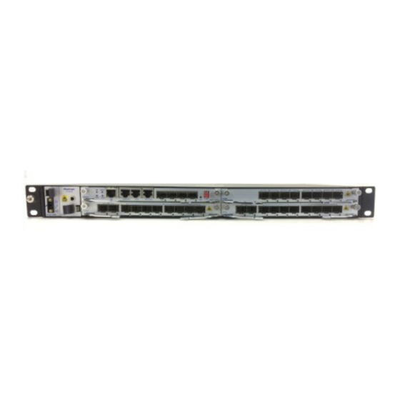
Page 19: Hardware Architecture
HT8000-I/HT8000-II/HT8000-VI devices use plug-in design. All cards in the chassis are installed horizontally at the front of the chassis and support hot swapping. HT8000-I chassis provides four slots for cards. Slot layout is shown in Figure 2-1. Figure 2-1 Slot layout of HT8000-I... - Page 20 OSC channel and EXP port D1GH-S-LD2136 Slot 4 16 channels (D21-D36) DWDM MUX/DEMUX card with 1510nm OSC channel, occupying 2 slots D1GD-S-LD2132 Slot 4 12 channels (D21-D32) DWDM with OSC MUX/DEMUX card channel , occupying 2 slots Beijing Huahuan Electronics Co., Ltd. Version 1.4(Oct.2019)
- Page 21 OSC channel and EXP port D1G8-SE-LD4552 Slot 3/4/5 8 channels (D45-D52) DWDM MUX/DEMUX card with 1510nm OSC channel and EXP port D1G8-SE-LD5360 Slot 3/4/5 8 channels (D53-D60) DWDM MUX/DEMUX card with 1510nm OSC channel and EXP port Version 1.4(Oct.2019) Beijing Huahuan Electronics Co., Ltd.
- Page 22 60km DCF card, occupying 2 slots B1FN-80 Slot 4 80km DCF card, occupying 2 slots P1P1 Slot 3/4/5 1+1 Optical line protection card P1P1-M Slot 1 1+1 Optical line protection card, supporting management function Beijing Huahuan Electronics Co., Ltd. Version 1.4(Oct.2019)
- Page 23 Preamplifier, with Mon port A1PS-MC-P12 Slot 1 Single channel, +12dBm Preamplifier, with Mon port and management port A2GS-NM-P21.P12 Slot 3/4/5 Single channel, noise application, integrated +21dBm BA and +12dBm PA, with Mon port Version 1.4(Oct.2019) Beijing Huahuan Electronics Co., Ltd.
-
Page 24: Figure 2-2 Slot Layout Of Ht8000- Ii
6 fans card for 2U/6U chassis Slot 3/4/5/6/7/8 4 channels OSC card with external NM, BITs, and alarm port O2A8-D Slot 3/4/5/6/7/8 2XOTU2+8xAnyrate muxponder with ODU switch O4M4 Slot 3/4/5/6/7/8 4XOTU+2 multi-rate transponder Beijing Huahuan Electronics Co., Ltd. Version 1.4(Oct.2019) - Page 25 EXP port D1G8-SE-LD2936 Slot 3/4/5/6/7/8 8 channels (D29-D36) DWDM MUX/DEMUX card with 1510nm OSC channel and EXP port 8 channels (D37-D44) D1G8-SE-LD3744 Slot 3/4/5/6/7/8 DWDM MUX/DEMUX card with 1510nm OSC channel and EXP port Version 1.4(Oct.2019) Beijing Huahuan Electronics Co., Ltd.
- Page 26 OSC channel, occupying 2 slots D1GD-S-LD2132 Slot 5/6/7/8 12 channels (D21-D32) DWDM with OSC MUX/DEMUX card channel , occupying 2 slots D1GD-S-LD3344 Slot 5/6/7/8 12 channels (D33-D44) DWDM with OSC MUX/DEMUX card channel , occupying 2 slots Beijing Huahuan Electronics Co., Ltd. Version 1.4(Oct.2019)
- Page 27 Slot 5/6/7/8 40km DCF card, occupying 2 slots B1FN-60 Slot 5/6/7/8 60km DCF card, occupying 2 slots B1FN-80 Slot 5/6/7/8 80km DCF card, occupying 2 slots P1P1 Slot 3/4/5/6/7/8 1+1 Optical line protection card Version 1.4(Oct.2019) Beijing Huahuan Electronics Co., Ltd.
- Page 28 A2GS-NM-P21.P12 Slot 3/4/5/6/7/8 Single channel, Low noise application, integrated +21dBm BA and +12dBm PA, with Mon port HT8000-VI chassis provides twenty-four slots for cards. Slot layout is shown in Figure 2-3. Beijing Huahuan Electronics Co., Ltd. Version 1.4(Oct.2019)
-
Page 29: Figure 2-3 Slot Layout Of Ht8000- Vi
2 OSC channels MC02 Slot 30/31 Expandable chassis cascade card, HT8000-VI includes 2 MC02 cards by default FPS7-D48 Slot 28/29 48V DC power supply unit FFT6 Slot 25/26/27 6 fans card for 1RU chassis Version 1.4(Oct.2019) Beijing Huahuan Electronics Co., Ltd. - Page 30 MUX/DEMUX card 3-channel, single-fiber, 2-way C1G3-BSE-LC2737 Slot 3/4/5/6/7/8/9/10/11/12/13/14/ 15/16/17/18/19/20/21/22/23/24 CWDM MUX/DEMUX card with OSC channel and EXP port 3-channel, single-fiber, 2-way C1G3-BSE-LC3727 Slot 3/4/5/6/7/8/9/10/11/12/13/14/ 15/16/17/18/19/20/21/22/23/24 CWDM MUX/DEMUX card with OSC channel and EXP port Beijing Huahuan Electronics Co., Ltd. Version 1.4(Oct.2019)
- Page 31 5/6/7/8/11/12/13/14/15/ D1MF-S-LD2160 40 channels (D21-D60) 16/19/20/21/22/23/24 DWDM MUX card with 1510nm OSC channel, occupying 2 slots D1DF-S-LD2160 Slot 5/6/7/8/11/12/13/14/15/ 40 channels (D21-D60) 16/19/20/21/22/23/24 DWDM DEMUX card with 1510nm OSC channel, occupying 2 slots Version 1.4(Oct.2019) Beijing Huahuan Electronics Co., Ltd.
- Page 32 EXP port for OSC add/drop Slot 5/6/7/8/11/12/13/14/15/ B1FN-40 40km DCF card, occupying 2 16/19/20/21/22/23/24 slots B1FN-60 Slot 5/6/7/8/11/12/13/14/15/ 60km DCF card, occupying 2 16/19/20/21/22/23/24 slots B1FN-80 Slot 5/6/7/8/11/12/13/14/15/ 80km DCF card, occupying 2 16/19/20/21/22/23/24 slots NOTE Beijing Huahuan Electronics Co., Ltd. Version 1.4(Oct.2019)
-
Page 33: Card Introduction
The card occupying two slots is installed in the lower part of two slots it occupies. 2.2 Card Introduction This section describes the function and use of various cards on HT8000-I/HT8000-II/HT8000-VI. There are interfaces and indicators on the cards, indicating their running status, alarm status, and other status, which facilitates the on-site installation and commissioning. -
Page 34: Dc Power-Supply Card/100W (Fps1-D48)
It is only used in HT8000-I device. There is a PWR LED and two power interfaces on the front panel of FPS1-D48. The front panel diagram is shown in Figure 2-5, the PWR LED is described in Table 2-6, and the description of power interface is shown in Table 2-7. -
Page 35: Ac Power-Supply Card (Fps1-A220)
2.2.3 220V AC Power-supply Card (FPS1-A220) FPS1-A220 card is connected to the 220V power supply and provides protection against input under-voltage, input overvoltage, output overvoltage, output overcurrent, and over temperature. It supports hot swap and redundancy protection. Version 1.4(Oct.2019) Beijing Huahuan Electronics Co., Ltd. -
Page 36: 4-Channel Osc Card (Fs4)
The front panel diagram is shown in Figure 2-7, the LEDs are described in Table 2-9. Figure 2-7 The front panel diagram of FS4 OSC1 OSC2 OSC3 OSC4 LINK IN-1PPS TOD-OUT BITS Beijing Huahuan Electronics Co., Ltd. Version 1.4(Oct.2019) -
Page 37: Management Clock Card (Mc01)
MC01 provides 1 NM interface, 2 EXT interfaces, 1 CONSOLE interface, 1 BITS external clock input/output interface, 1PPS TOD interface, 2 OSC interfaces, 4 LEDs, 1 reset button and a set of 2-position dip switch. The Version 1.4(Oct.2019) Beijing Huahuan Electronics Co., Ltd. -
Page 38: Figure 2-8 The Front Panel Diagram Of Mc01
BUSY indication: On: synchronization acquisition Off: no data synchronized Green Green Ethernet optical port Link/Active indication: light at On: link up NM/EXT Blink: date transmitted in Ethernet optical ports port Off: link down Beijing Huahuan Electronics Co., Ltd. Version 1.4(Oct.2019) -
Page 39: Table 2-11 Dip Switch Functions
Figure 2-9, NM/EXT ports are FE electrical ports; see its socket definition in Table 2-13. CONSOLE port pin definition is shown in Table 2-14. Table 2-12 Marks and definitions of management ports Mark Definition NM/EXT Out-of-band management port Version 1.4(Oct.2019) Beijing Huahuan Electronics Co., Ltd. -
Page 40: Figure 2-9 Pin Definition Of Rj45 Connector
MC01 card provides 1-channel of external clock input/output port, supporting 2MHz, 2Mbit/s clock mode. It is marked with “BITS”, using RJ45 socket. RJ-45 connector diagram and pin definition are shown in Figure 2-9 and Table 2-15. Beijing Huahuan Electronics Co., Ltd. Version 1.4(Oct.2019) -
Page 41: Table 2-15 Definition Of External Clock Input\Output Ports
Figure 2-9 and Table 2-16. Table 2-16 1PPS+ToD port pin definition Definition Description RS-422_1_N 1PPS - RS-422_1_P 1PPS+ RS-422_2_N TOD time information RS-422_2_P TOD time information Version 1.4(Oct.2019) Beijing Huahuan Electronics Co., Ltd. -
Page 42: Expandable Chassis Cascade Card (Mc02)
MC02 provides a green LED (RUN) to indicate its operational status, blinking means running normally, off means running abnormally or unpowered. The front panel diagram of MC02 is shown in Figure 2-11. Figure 2-11 The front panel diagram of MC02 MC02 Beijing Huahuan Electronics Co., Ltd. Version 1.4(Oct.2019) -
Page 43: Anyrate+2 Otu Muxponder Card (O2A8-D)
SFP/SFP+ optical module or single-fiber SFP/SFP+ optical module. The front panel diagram is shown in Figure 2-13, the LED is described in Table 2-17. Figure 2-13 The front panel diagram of O2A8-D O2A8-D Version 1.4(Oct.2019) Beijing Huahuan Electronics Co., Ltd. -
Page 44: 4-Channel Transponder Card (O4M4)
LC dual-fiber SFP+ optical module or single-fiber SFP+ optical module. The front panel diagram is shown in Figure 2-14, the LED is described in Table 2-18. Figure 2-14 The front panel diagram of O4M4 O4M4 Beijing Huahuan Electronics Co., Ltd. Version 1.4(Oct.2019) -
Page 45: 2-Channel Transponder Card (O2M2-P)
LC dual-fiber SFP+ optical module or single-fiber SFP+ optical module. The front panel diagram is shown in Figure 2-15, the LED is described in Table 2-19. Figure 2-15 The front panel diagram of O2M2-P O2M2-P O2M2-P Version 1.4(Oct.2019) Beijing Huahuan Electronics Co., Ltd. -
Page 46: 16-Channel Dwdm Mux/Demux Card (D1Gh-S-Ld2136)
D21 D22 D23 D24 D25 D26 D27 D28 D29 D30 D31 D32 D33 D34 D35 D36 D1GH-S-LD2136 Table 2-20 LED functional descriptions of D1GH-S-LD2136 Color Descriptions Green System running indication: On: running normally Off: running abnormally Beijing Huahuan Electronics Co., Ltd. Version 1.4(Oct.2019) -
Page 47: 8-Channel Dwdm Mux/Demux Card (D1G8-Se-Ld2128/D1G8-Se-Ld2936/D1G8-Se-Ld3744/D1G8-Se-Ld4552/D1G8-S E-Ld5360)
The front panel diagrams are shown in Figure 2-17, the LED is described in Table 2-21. Figure 2-17 The front panel diagram of D1G8-SE-LD2128/ D1G8-SE-LD2936/D1G8-SE-LD3744/D1G8-SE-LD4552/D1G8-SE-LD5360 IN OUT IN OUT IN OUT IN OUT IN OUT OUT IN D1G8-SE-LD2128 Version 1.4(Oct.2019) Beijing Huahuan Electronics Co., Ltd. -
Page 48: Table 2-21 Led Functional Descriptions Of D1G8-Se-Ld2128/ D1G8-Se-Ld2936/D1G8-Se-Ld3744/D1G8-Se-Ld4552/D1G8-Se-Ld5360
OSC interfaces are used to input/output supervisory signals, EXP interfaces are the cascaded input/output interfaces and COM interfaces are used to output/input multiplexed signals. Beijing Huahuan Electronics Co., Ltd. Version 1.4(Oct.2019) -
Page 49: 12-Channel Dwdm Mux/Demux Card (D1Gd-S-Ld2132/D1Gd-S-Ld3344/D1Gd-S-Ld4556)
D37 D38 D39 D40 D41 D42 D43 D44 D1GD-S-LD3344 D45 D46 D47 D48 D49 D50 D51 D52 D53 D54 D55 D56 COM OSC D45 D46 D47 D48 D49 D50 D51 D52 D53 D54 D55 D56 D1GD-S-LD4556 Version 1.4(Oct.2019) Beijing Huahuan Electronics Co., Ltd. -
Page 50: 40-Channel Dwdm Mux Card (D1Mf-S-Ld2160)
D25 D26 D27 D28 D29 D30 D31 D32 D33 D34 D35 D36 D38 D39 D40 D41 D42 D43 D44 D45 D46 D47 D48 D49 D50 D51 D52 D53 D54 D55 D56 D57 D58 D59 D60 D1MF-S-LD2160 Beijing Huahuan Electronics Co., Ltd. Version 1.4(Oct.2019) -
Page 51: 40-Channel Dwdm Demux Card (D1Df-S-Ld2160)
D25 D26 D27 D28 D29 D30 D31 D32 D33 D34 D35 D36 D38 D39 D40 D41 D42 D43 D44 D45 D46 D47 D48 D49 D50 D51 D52 D53 D54 D55 D56 D57 D58 D59 D60 D1DF-S-LD2160 Version 1.4(Oct.2019) Beijing Huahuan Electronics Co., Ltd. -
Page 52: 8-Channel Cwdm Mux/Demux Card (C1G8-S-Lc4761)
IN OUT IN OUT IN OUT IN OUT IN OUT C1G8-S-LC4761 1511 1531 1551 1571 1591 1611 1471 1491 The number under each optical port is the wavelength accessible to the optical port. Beijing Huahuan Electronics Co., Ltd. Version 1.4(Oct.2019) -
Page 53: 10-Channel Cwdm Mux/Demux Card (C1Gx-Lc4361)
IN OUT IN OUT IN OUT IN OUT 1591 1611 C1GX-LC4361 1431 1451 1471 1491 1511 1531 1551 1571 The number under each optical port is the wavelength accessible to the optical port. Version 1.4(Oct.2019) Beijing Huahuan Electronics Co., Ltd. -
Page 54: 2-Channel, Single-Fiber, 2-Way Mux/Demux Card(C1G2-Bse-Lc5157
The front panel diagram of C1G2-BSE-LC5157 is shown in Table 2-22, the LED is described in Table 2-27. Figure 2-23 The front panel diagram of C1G2-BSE-LC5157 C1G2-BSE-LC5157 EXP 1430 1450 1510 1530 1550 1570 Beijing Huahuan Electronics Co., Ltd. Version 1.4(Oct.2019) -
Page 55: 2-Way, Single Ch Cwdm Card (C2G1-E-Lc51)
C2G1-E-LC51 is a 2-way 1510nm CWDM filtering card with EXP port for OSC add/drop. C2G1-E-LC51 supports CWDM technical specifications. The front panel diagram of C2G1-E-LC51 is shown in Figure 2-24, the LED is described in Table 2-28. Version 1.4(Oct.2019) Beijing Huahuan Electronics Co., Ltd. -
Page 56: 3-Channel, Single-Fiber, 2-Way Cwdm Mux/Demux Card (C1G3-Bse-Lc2737/ C1G3-Bse-Lc3727)
C1G3-BSE-LC2737 and C1G3-BSE-LC3727 respectively provide an EXP port which can cascade other MUX/DEMUX cards to accomplish the multiplexing/de-multiplexing of remaining channels in the MUX signal. The front panel diagrams of C1G3-BSE-LC2737/ C1G3-BSE-LC3727 are shown in Figure 2-25. Beijing Huahuan Electronics Co., Ltd. Version 1.4(Oct.2019) -
Page 57: C-Band, Pre+Boost Edfa (A2Gc-Sm-P21.P17/ A2Gc-Sm-P17.P12)
A2GC-SM-P17.P12 can realize amplification function of full C-band optical signal with integrated +17dBm BA and +12dBm PA. A2GC-SM-P21.P17/A2GC-SM-P17.P12 supports automatic gain control function, which has no effect on online service when increasing or decreasing the channel. Version 1.4(Oct.2019) Beijing Huahuan Electronics Co., Ltd. -
Page 58: Figure 2-26 The Front Panel Diagrams Of A2Gc-Sm-P21.P17/A2Gc-Sm-P17.P12
OUT IN OSC MON A2GC-SM-P17.P12 Table 2-29 LED functional descriptions of A2GC-SM-P21.P17/A2GC-SM-P17.P12 Color Descriptions Green System running indication: Blink: running normally Off: running abnormally Alarm status indication: On: alarm occurs Off: no alarm Beijing Huahuan Electronics Co., Ltd. Version 1.4(Oct.2019) -
Page 59: C-Band Raman Optical Amplifier Card (A1Rc-M-G14)
Figure 2-27 The front panel diagram of A1RC-M-G14 OUT IN PMON A1RC-M-G14 Table 2-30 LED functional descriptions of A1RC-M-G14 Color Descriptions Green System running indication: Blink: running normally Off: running abnormally Alarm status indication: On: alarm occurs Off: no alarm Version 1.4(Oct.2019) Beijing Huahuan Electronics Co., Ltd. -
Page 60: C-Band Raman Optical Amplifier Card (A1Rc-Mc-G14)
Figure 2-28, 2 LEDs are described in Table 2-31. Figure 2-28 The front panel diagram of A1RC-MC-G14 OUT IN PMON CONSOLE A1RC-MC- Table 2-31 LED functional descriptions of A1RC-MC-G14 Color Descriptions Green System running indication: Blink: running normally Off: running abnormally Beijing Huahuan Electronics Co., Ltd. Version 1.4(Oct.2019) -
Page 61: Single Ch, Pre+Boost Edfa (A2Gs-M-P17.P12)
Figure 2-29 The front panel diagram of A2GS-M-P17.P12 OUT IN NC MON OUT IN NC MON A2GS-M-P17.P12 Table 2-32 LED functional descriptions of A2GS-M-P17.P12 Color Descriptions Green System running indication: Blink: running normally Off: running abnormally Version 1.4(Oct.2019) Beijing Huahuan Electronics Co., Ltd. -
Page 62: Single Ch, Boost Amplifier Card (A1Bs-Mc-P17)
1 CONSOLE interface are used as monitoring interfaces, 1 OSC interface is used to supervise channel signal transmission. The front panel diagram is shown in Figure 2-30, 3 LEDs are described in Table 2-33. Beijing Huahuan Electronics Co., Ltd. Version 1.4(Oct.2019) -
Page 63: Single Ch, Boost Amplifier Card (A1Bs-M-P17)
+17dBm boost amplifier. A1BS-M-P17 supports automatic gain control function, which has no effect on online service when increasing or decreasing the channel. A1BS-M-P17 provides an MON port for on-line monitor optical signals. Version 1.4(Oct.2019) Beijing Huahuan Electronics Co., Ltd. -
Page 64: Single Ch, Preamplifier Card (A1Ps-Mc-P12)
2.2.26 Single CH, Preamplifier Card (A1PS-MC-P12) A1PS-MC-P12 can realize amplification function of single channel optical signal with +12dBm preamplifier. A1PS-MC-P12 supports automatic gain control function, which has no effect on online service when increasing or decreasing the channel. Beijing Huahuan Electronics Co., Ltd. Version 1.4(Oct.2019) -
Page 65: Figure 2-32 The Front Panel Diagram Of A1Ps-Mc-P12
Figure 2-32 The front panel diagram of A1PS-MC-P12 CONSOLE A1PS-MC-P12 Table 2-35 LED functional descriptions of A1PS-MC-P12 Color Descriptions Green System running indication: Blink: running normally Off: running abnormally Alarm status indication: On: alarm occurs Off: no alarm Version 1.4(Oct.2019) Beijing Huahuan Electronics Co., Ltd. -
Page 66: Single Ch, Preamplifier Card (A1Ps-M-P12)
1 IN interface is used to input signals to be amplified. The front panel diagram is shown in Figure 2-33, 2 LEDs are described in Table 2-36. Figure 2-33 The front panel diagram of A1PS-M-P12 A1PS-M-P12 Beijing Huahuan Electronics Co., Ltd. Version 1.4(Oct.2019) -
Page 67: Single Ch, Low Noise, Pre+Boost Edfa (A2Gs-Nm-P21.P12)
The front panel diagram is shown in Figure 2-34, 2 LEDs are described in Table 2-37. Figure 2-34 The front panel diagram of A2GS-NM-P21.P12 OUT IN NC MON OUT IN NC MON A2GS-NM-P21.P12 Version 1.4(Oct.2019) Beijing Huahuan Electronics Co., Ltd. -
Page 68: 40/60/80Km Dcf Card (B1Fn-40/B1Fn-60/B1Fn-80)
B1FN-80 provides 80km compensation distance. B1FN-40/B1FN-60/B1FN-80 has 1 LED, 1 OUT interface and 1 IN interface. The front panel diagrams are shown in Figure 2-35, the LED is described in Table 2-38. Beijing Huahuan Electronics Co., Ltd. Version 1.4(Oct.2019) -
Page 69: Single Ch 1+1 Olp Card (P1P1)
On the front panel of P1P1 card, there are five LEDs. UNI side provides an RO interface and a TI interface. NNI side MASTE channel provides a TO1 Version 1.4(Oct.2019) Beijing Huahuan Electronics Co., Ltd. -
Page 70: Figure 2-36 The Front Panel Diagram Of P1P1
Off: the received optical power is higher than threshold UNI side optical signal receiving indication: On: the received optical power is lower than threshold Off: the received optical power is higher than threshold Beijing Huahuan Electronics Co., Ltd. Version 1.4(Oct.2019) - Page 71 NNI-side TO1 and TO2 interfaces. RO interface (connecting to RX interface of UNI-side device) outputs optical signal which received by NNI-side RI1 and RI2 interfaces to the UNI-side RX interface. Version 1.4(Oct.2019) Beijing Huahuan Electronics Co., Ltd.
-
Page 72: Single Ch 1+1 Olp Card (P1P1-M)
Figure 2-37 The front panel diagram of P1P1-M MASTER SLAVE SLAVE MASTER P1P1-M CONSOLE Table 2-40 LED functional descriptions of P1P1-M Color Descriptions Green System running indication: Blink: running normally Off: running abnormally Beijing Huahuan Electronics Co., Ltd. Version 1.4(Oct.2019) - Page 73 Off: the received optical power is higher than threshold UNI-side optical signal receiving indication: On: the received optical power is lower than threshold Off: the received optical power is higher than threshold Version 1.4(Oct.2019) Beijing Huahuan Electronics Co., Ltd.
- Page 74 NNI-side RI1 and RI2 interfaces to the UNI-side RX interface. Management Ports P1P1-M provides 1 NM port and 1 CONSOLE port as its network management ports, marks and definitions are shown in Table 2-12. Beijing Huahuan Electronics Co., Ltd. Version 1.4(Oct.2019)
-
Page 75: Single Ch 1:1 Olp Card (P1R1)
Figure 2-38 The front panel diagram of P1R1 MASTER SLAVE SLAVE MASTER RI1 TO2 P1R1 Table 2-41 LED functional descriptions of P1R1 Color Descriptions Green System running indication: Blink: running normally Off: running abnormally Version 1.4(Oct.2019) Beijing Huahuan Electronics Co., Ltd. - Page 76 MASTER channel is higher than threshold Optical signal receiving indication: RI SLAVE On: the optical power received by SLAVE channel is lower than threshold Off: the optical power received by SLAVE channel higher than threshold Beijing Huahuan Electronics Co., Ltd. Version 1.4(Oct.2019)
- Page 77 RI2 interface of NNI-side SLAVE channel. TI interface (connecting to TX interface of UNI-side device) inputs UNI-side TX signal and transmits it to TO2 interface of NNI-side SLAVE channel. SEC: the optical path with low-priority Version 1.4(Oct.2019) Beijing Huahuan Electronics Co., Ltd.
-
Page 78: Single Ch 1:1 Olp Card (P1R1-M)
RI1 interface; SLAVE channel provides a TO2 interface and an RI2 interface. The front panel diagram is shown in Figure 2-40, LEDs are described in Table 2-43. Figure 2-39 The front panel diagram of P1R1-M MASTER SLAVE SLAVE MASTER RI1 TO2 CONSOLE P1R1-M Beijing Huahuan Electronics Co., Ltd. Version 1.4(Oct.2019) -
Page 79: Table 2-42 Led Functional Descriptions Of P1R1-M
Optical port signal state indication: On: optical signal loss Off: optical signal is received NNI-side optical signal receiving indication: On: the received optical power is lower than threshold Off: the received optical power is higher than threshold Version 1.4(Oct.2019) Beijing Huahuan Electronics Co., Ltd. - Page 80 PRI: The optical path with high-priority RO interface (connecting to RX interface of UNI-side device) outputs optical signal which received by RI1 interface of NNI-side MASTER channel to the RX interface of UNI-side PRI channel. Beijing Huahuan Electronics Co., Ltd. Version 1.4(Oct.2019)
-
Page 81: Single Ch 1:1 Olp Card (P1R1-P)
2.2.34 Single CH 1:1 OLP Card (P1R1-P) P1R1-P is a 1:1 optical line protection card. It supports automatic /forced/manual switching modes in case of service interruption caused by fiber line deterioration or interruption. Version 1.4(Oct.2019) Beijing Huahuan Electronics Co., Ltd. -
Page 82: Figure 2-40 The Front Panel Diagram Of P1R1-P
OSC-E P1R1-P Table 2-43 LED functional descriptions of P1R1-P Color Descriptions Green System running indication: Blink: running normally Off: running abnormally Alarm status indication: On: alarm occurs to the card Off: no alarm Beijing Huahuan Electronics Co., Ltd. Version 1.4(Oct.2019) - Page 83 Off: the received optical power is higher than threshold NNI-side CHL1 channel optical signal CHL1 receiving indication: On: the received optical power is lower than threshold Off: the received optical power is higher than threshold Version 1.4(Oct.2019) Beijing Huahuan Electronics Co., Ltd.
- Page 84 TI interface (connecting to TX interface of UNI-side device) inputs TX signal of UNI-side low-priority device and transmits it to TO2 interface of NNI-side protection channel. When the working channel fails, like the fiber is broken: Beijing Huahuan Electronics Co., Ltd. Version 1.4(Oct.2019)
-
Page 85: Single Ch 1:1 Olp Card (P1R1-Mp)
On the front panel of P1R1-MP card, there is an NM interface, a CONSOLE interface, two OSC optical interfaces and six LEDs. The PRI channel and SEC channel on the UNI side respectively provide an RO Version 1.4(Oct.2019) Beijing Huahuan Electronics Co., Ltd. -
Page 86: Figure 2-41 The Front Panel Diagram Of P1R1-Mp
Ethernet port Speed indication: NM port On: link to 100M Off: link to 10M or link down Blink: date transmitted in Ethernet port Alarm status indication: On: alarm occurs to the card Off: no alarm Beijing Huahuan Electronics Co., Ltd. Version 1.4(Oct.2019) - Page 87 Off: the received optical power is higher than threshold CHL1 NNI-side CHL1 channel optical signal receiving indication: On: the received optical power is lower than threshold Off: the received optical power is higher than threshold Version 1.4(Oct.2019) Beijing Huahuan Electronics Co., Ltd.
- Page 88 TI interface (connecting to TX interface of UNI-side device) inputs TX signal of UNI-side low-priority device and transmits it to TO2 interface of NNI-side protection channel. When the working channel fails, like the fiber is broken: Beijing Huahuan Electronics Co., Ltd. Version 1.4(Oct.2019)
-
Page 89: 3-Fan Card (Fft30)/6-Fan Card (Fft6)
Table 2-13. CONSOLE port pin definition is shown in Table 2-14. 2.2.36 3-fan Card (FFT30)/6-fan Card (FFT6) FFT30 is a 3-fan card for HT8000-I device; FFT6 is a 6-fan card for HT8000-II/HT8000-VI device. FFT3/FFT6 provides heat dissipation function for the equipment, making it operates normally and efficiently at the designed temperature. -
Page 90: Figure 2-42 The Front Panel Diagrams Of Fft3/Fft6
The front panel diagrams are shown in Figure 2-42. Figure 2-42 The front panel diagrams of FFT3/FFT6 HT8000 E S D E S D FFT6 Beijing Huahuan Electronics Co., Ltd. Version 1.4(Oct.2019) -
Page 91: Deployment And Maintenance
3.1.1 IP Address/Subnet Mask Query and Settings HT8000-I/HT8000-II/HT8000-VI device needs to log in Telnet via Ethernet monitoring interface for IP address query and setting. If the factory out-of-band IP address is modified and the current address is forgotten, you can log in hyper terminal via CONSOLE monitoring interface to get the real address of the device. -
Page 92: Monitoring Software
For detailed usage of network management monitoring software, please refer to the online help of network management software. For security reasons, you’d better change the password in time when you use the device for the first time. Beijing Huahuan Electronics Co., Ltd. Version 1.4(Oct.2019) -
Page 93: Cable Introduction
4.1.1 Fiber Types The connector and required length of the optical fiber should be selected according to site survey results. Table 4-1 Fiber types Types Parameters LC/PC Simple module-G.657 SC/PC Simple module-G.657 FC/PC Simple module-G.657 Version 1.4(Oct.2019) Beijing Huahuan Electronics Co., Ltd. -
Page 94: Ht8000-I/Ht8000-Ii/Ht8000-Vi
SC/PC type and FC/PC type fiber connector. Table 4-2 Fiber connector types Types Descriptions LC/PC Clamped square optical fiber connector SC/PC Square optical fiber connector FC/PC Circular optical fiber connector Figure 4-1 LC/PC fiber connector Beijing Huahuan Electronics Co., Ltd. Version 1.4(Oct.2019) -
Page 95: Power Cord
HT8000-I/HT8000-II/HT8000-VI 4 Cable Introduction Figure 4-2 SC/PC fiber connector Figure 4-3 FC/PC fiber connector 4.2 Power Cord Please align the DC power cord head to the socket and insert it with moderate force. Version 1.4(Oct.2019) Beijing Huahuan Electronics Co., Ltd. -
Page 96: Management Cable
4.3 Management Cable 4.3.1 Straight-through Network Cable Both ends of the straight-through network cable are RJ-45 connectors, respectively connecting devices at both ends. Structure structure of straight-through network cable is shown in Figure 4-5. Beijing Huahuan Electronics Co., Ltd. Version 1.4(Oct.2019) -
Page 97: Figure 4-5 The Structure Of Straight-Through Network Cable
Table 4-3 Pin assignments of straight-through network cable Connector X1 Connector X2 Relationship X1.2 X2.2 Pair X1.1 X2.1 X1.6 X2.6 Pair X1.3 X2.3 X1.4 X2.4 Pair X1.5 X2.5 X1.8 X2.8 Pair X1.7 X2.7 Version 1.4(Oct.2019) Beijing Huahuan Electronics Co., Ltd. -
Page 98: Crossover Network Cable
Both ends of the crossover network cable are RJ-45 connectors, respectively connecting devices at both ends. Structure structure of crossover network cable is shown in Figure 4-6. Figure 4-6 The structure of crossover network cable Beijing Huahuan Electronics Co., Ltd. Version 1.4(Oct.2019) - Page 99 Technical Specifications Table 4-6 Technical specifications of crossover network cable Items Descriptions Connector X1/X2 Network port connector-8PIN-8bit-shield- crystal plug Cable type Symmetrical twisted-pair cable-100ohm- enhanced Category-5 cable, aluminum foil shield-0.52mm-24AWG-8 cores 4 pairs-PANTONE 430U Version 1.4(Oct.2019) Beijing Huahuan Electronics Co., Ltd.
- Page 100 User's Manual 4 Cable Introduction HT8000-I/HT8000-II/HT8000-VI Items Descriptions Quantity of cores Beijing Huahuan Electronics Co., Ltd. Version 1.4(Oct.2019)
-
Page 101: Technique Specifications
Technique Specifications 5.1 Monitoring Ports SNMP port Plug RJ-45 Rate 10/100M Port protocol SNMP protocol Console port Plug RJ-45 Electrical specification RS-232 5.2 External Clock Input/Output Port Specification Description 2MHz,2Mbit/s External clock input Version 1.4(Oct.2019) Beijing Huahuan Electronics Co., Ltd. -
Page 102: External Time Synchronization Port
RJ45 5.4 Wavelength Conversion Service Port Items Description 100Mbit/s~10Gbit/s UNI-side port rate Plug O2A8-D: SFP/SFP+ O4M4/O2M2-P: SFP+ Optical interface It depends on the optical module technical parameters Items Description NNI-side port rate 10Gbit/s Beijing Huahuan Electronics Co., Ltd. Version 1.4(Oct.2019) -
Page 103: Dwdm Mux/Demux Port
Operating frequency range 192.10~196.00 Adjacent channel separation The working wavelength of 1510 1510nm channel ≤0.9 Insertion loss ≤3.8 DWDM ≤7.6 2-way D1G8-SE-LD2128/D1G8-SE-LD2936/D1G8-SE-LD3744/D1G8-SE-LD 4552/D1G8-SE-LD5360 Card Items Unit Specification 192.10~196.00 Operating frequency range Adjacent channel Version 1.4(Oct.2019) Beijing Huahuan Electronics Co., Ltd. - Page 104 Adjacent channel separation The working wavelength of 1510 1510nm channel ≤0.8 Insertion loss ≤6.5 DWDM D1GD-S-LD2132/D1GD-S-LD3344/D1GD-S-LD4556 Items Unit Specification Operating frequency range 192.10~196.00 Adjacent channel separation The working wavelength of 1510 1510nm channel Beijing Huahuan Electronics Co., Ltd. Version 1.4(Oct.2019)
-
Page 105: Cwdm Mux/Demux Port
Specification Wavelength channel 1470/1490/1510/1530/1550 /1570/1590/1610, OSC:1450 Adjacent channel separation ≤3.0 Insertion CWDM loss ≤3.9 2-way ≤3.3 ≤6.6 OSC 2-way C1GX-LC4361 Card Items Unit Specification Wavelength channel 1431~1611 Adjacent channel separation ≤4.5 Insertion CWDM Version 1.4(Oct.2019) Beijing Huahuan Electronics Co., Ltd. - Page 106 ≤1.2 Insertion 1430,1450 loss (OSC) ≤2.2 1510-1570 ≤2.0 C2G1-E-LC51 Card Items Unit Specification Operating wavelength 1270~1610 range Adjacent channel separation ≤0.9 Insertion 1510 loss ≤0.7 C1G3-BSE-LC2737/C1G3-BSE-LC3727 Card Items Unit Specification Operating wavelength 1260~1620 Beijing Huahuan Electronics Co., Ltd. Version 1.4(Oct.2019)
-
Page 107: Optical Booster Amplifier Port
5.7 Optical Booster Amplifier Port A2GC-SM-P21.P17 Card Items Unit Specification 1529~1567 Working wavelength range -21~0 Total input power range Maximum total output power ≤6.2 Noise figure 9-21 Channel gains RL (return loss) Polarization dependent gain Version 1.4(Oct.2019) Beijing Huahuan Electronics Co., Ltd. - Page 108 Working wavelength range 1528.5~1562 Total input power range -22~-5 Maximum total output power ≤6.2 Noise figure Channel gains 18-22 RL (return loss) Polarization dependent gain A1PS-MC-P12/A1PS-M-P12 Card Items Unit Specification Working wavelength range 1528.5~1562 Beijing Huahuan Electronics Co., Ltd. Version 1.4(Oct.2019)
- Page 109 Polarization dependent gain A2GS-NM-P21.P12 Card Items Unit Specification Working wavelength range 1550.12 Total input power range -22~0 Maximum total output power ≤5.7 Noise figure Channel gains 18-21 RL (return loss) Polarization dependent gain Version 1.4(Oct.2019) Beijing Huahuan Electronics Co., Ltd.
-
Page 110: Optical Preamplifier Port
Polarization dependent gain A2GC-SM-P17.P12 Card Items Unit Specification Working wavelength range 1529~1567 Total input power range -35~-8 Maximum total output power ≤5.5 Noise figure Channel gains 20-30 RL (return loss) Polarization dependent gain Beijing Huahuan Electronics Co., Ltd. Version 1.4(Oct.2019) - Page 111 RL (return loss) Polarization dependent gain A2GS-NM-P21.P12 Card Items Unit Specification Working wavelength range 1550.12 Total input power range -45~-25 Maximum total output power ≤4.5 Noise figure RL (return loss) Polarization dependent gain Version 1.4(Oct.2019) Beijing Huahuan Electronics Co., Ltd.
-
Page 112: Raman Optical Amplifier Card
PMON 0.5% RL (return loss) Polarization dependent gain 5.10 Dispersion Compensation Optical Fibers Distance Max. DSCR Max. Operating Insertion Allowed Wavelength Module (km) (dB) Power Loss (dB) (ps) (nm) (dBm) 90%~ 1525~1568 DCM(B) Beijing Huahuan Electronics Co., Ltd. Version 1.4(Oct.2019) -
Page 113: Optical Line Protection Port
RI1-RO <1.5 RI2-RO Working wavelength 1260~1640 range RL (return loss) >45 Polarization dependent <0.1 loss Power monitoring range Transmitting: -30~+25 Receiving: -50~+10 Switching time <50 Optical power difference +0.5 Switching type Power-down holdover Version 1.4(Oct.2019) Beijing Huahuan Electronics Co., Ltd. -
Page 114: Physical/Electrical Specifications
Switching type Power-down holdover 5.12 Physical/Electrical Specifications Physical/electrical specifications Dimensions HT8000-I: 44mm× 253mm× 442mm (H× D× W) HT8000-II: 88mm× 253mm× 442mm (H× D× W) HT8000-VI: 264mm× 253mm× 442mm (H× D× W) DC power supply FPS7-D48: -48V (-36V ~ -60V)/700W FPS1-D48: -48V (-36V ~ -60V)/100W FPS1-A220: AC 220V (165V ~ 265V) Beijing Huahuan Electronics Co., Ltd. - Page 115 User's Manual HT8000-I/HT8000-II/HT8000-VI 5 Technique Specifications Physical/electrical specifications Power HT8000-I maximum power consumption (typical consumption configuration): 125W HT8000-II maximum power consumption (typical configuration): 250W HT8000-VI maximum power consumption (typical configuration): 875W Operating 0° C~45° C temperature operating 10-90%RH (non-condensation) humidity Version 1.4(Oct.2019)
-
Page 116: Appendix Terms And Abbreviations
DWDM is an optical signal transmission technology Wavelength utilizing high bandwidth and low loss characteristics Division of single-mode fibers. Multiple optical carrier Multiplex(DWD channels with specific wavelength spacing can be combined and transmitted within a single optical fiber. Beijing Huahuan Electronics Co., Ltd. Version 1.4(Oct.2019) - Page 117 Supervisory optical channel for supervisory communication Channel(OSC) between different WDM nodes. User Network The interface between a user's device and a private Interface (UNI) or public network device, such as an ATM switch. Version 1.4(Oct.2019) Beijing Huahuan Electronics Co., Ltd.
- Page 118 Building Integrated Timing Supply CWDM Coarse Wavelength Division Multiplexing Data Communication Channel DWDM Dense Wavelength Division Multiplexing) Electric Supervisory Channel Network Node Interface Non-Return to Zero Optical Supervisory Channel Optical Transport Network Optical Transponder Unit Beijing Huahuan Electronics Co., Ltd. Version 1.4(Oct.2019)
- Page 119 User's Manual HT8000-I/HT8000-II/HT8000-VI Appendix Terms and Abbreviations Relative Humidity RMON Remote Network Monitoring Small Form-factor Pluggable SNMP Simple Network Management Protocol User Network Interface Wavelength Division Multiplexing Version 1.4(Oct.2019) Beijing Huahuan Electronics Co., Ltd.
Need help?
Do you have a question about the HT8000-I and is the answer not in the manual?
Questions and answers