Sign In
Upload
Manuals
Brands
HP Manuals
Switch
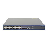
A5120-24G EI TAA
HP A5120-24G EI TAA Manuals
Manuals and User Guides for HP A5120-24G EI TAA. We have
1
HP A5120-24G EI TAA manual available for free PDF download: Installation Manual
HP A5120-24G EI TAA Installation Manual (91 pages)
Brand:
HP
| Category:
Switch
| Size: 4.43 MB
Table of Contents
3
Table of Contents
6
Preparing for Installation
7
Safety Recommendations
7
Installation Site Requirements
8
Rack-Mounting Requirements
8
Installation Tools
9
Installing the Switch
10
Rack-Mounting the A5120 EI Switch in a 19-Inch Rack
10
Mounting Brackets
12
Rack-Mounting Using Only Front Mounting Brackets
13
Rack-Mounting Using Front Mounting Brackets and a Rack Shelf
13
Rack-Mounting By Using Front and Rear Mounting Brackets
18
Rack-Mounting the A5120 SI Switch in a 19-Inch Rack
18
Mounting Brackets and Mounting Positions
18
Attaching the Mounting Brackets to the Switch Chassis
20
Rack-Mounting Procedure
22
Mounting the Switch On a Workbench
23
Grounding the Switch
23
Grounding to a Grounding Strip
25
Grounding to a Buried Grounding Conductor
26
Grounding Through the AC Power Cord
27
Connecting the Power Cord
27
Connecting the AC Power Cord
28
Connecting the Switch to a +12 VDC Output RPS
29
Connecting the Switch to a -52 to -55 VDC Output RPS
30
Installing/Removing an Interface Card (A5120 EI Switches Only)
30
Installing an Interface Card
31
Removing an Interface Card
31
Installing/Removing a Dedicated CX4/SFP+ Cable
32
Verifying the Installation
33
Accessing the Switch for the First Time
33
Setting Up the Configuration Environment
33
Connecting the Console Cable
33
Console Cable
34
Connection Procedure
34
Setting Terminal Parameters
37
Powering On the Switch
37
Verification before Power-On
37
Power-On Sequence
40
Changing the Startup Mode
42
Setting Up an IRF Fabric
42
IRF Fabric Setup Flowchart
43
Planning IRF Fabric Setup
43
Planning IRF Fabric Size and the Installation Site
43
Identifying the Master Switch and Planning IRF Member Ids
44
Planning IRF Topology and Connections
45
Identifying Physical IRF Ports On the Member Switches
46
Planning the Cabling Scheme
49
Configuring Basic IRF Settings
49
Connecting the Physical IRF Ports
49
Accessing the IRF Fabric to Verify the Configuration
51
Maintenance and Troubleshooting
51
Password Loss
51
Console Login Password Loss
51
Boot ROM Password Loss
51
Power Supply Failure
53
Fan Failure (A5120 EI Switches Only)
53
Console Terminal Problems
54
Support and Other Resources
54
Contacting HP
54
Subscription Service
54
Related Information
54
Documents
54
Websites
55
Conventions
57
Appendix A Technical Specifications
57
Panel Views
57
A5120-24G EI (2 Slots)/A5120-24G EI TAA (2 Slots)
58
A5120-48G EI (2 Slots)/A5120-48G EI TAA (2 Slots)
59
A5120-24G Ei
60
A5120-48G Ei
61
A5120-24G-Poe+ EI (2 Slots)/A5120-24G-Poe+ EI TAA (2 Slots)
62
A5120-48G-Poe+ EI (2 Slots)/A5120-48G-Poe+ EI TAA (2 Slots)
62
A5120-16G Si
63
A5120-24G Si
63
A5120-48G Si
64
A5120-24G-Ppoe+ SI
65
A5120-24G-Poe+ SI
66
Technical Specifications
66
Chassis Dimensions and Weights
66
Ports and Interface Card Slots
67
Power Specifications
67
Power Input Types
67
AC Input Voltage Specifications
67
RPS DC Input Voltage Specifications and RPS Compatibility
68
Power Consumption Specifications for Non-Poe Switches
68
Power Consumption Specifications for Poe Switches
69
Cooling System
70
Appendix B Frus and Compatibility Matrixes
70
Interface Cards (A5120 EI Switches Only)
70
SFP/SFP+/XFP Transceiver Modules and SFP+/CX4 Cables (A5120 EI Switches Only)
71
GE SFP Transceiver Modules
72
10-GE SFP+ Transceiver Modules
72
SFP+ Cables
73
10-GE XFP Transceiver Modules
73
CX4 Cables
74
SFP Transceiver Modules and SFP Stacking Kit (Only for the A5120 SI Switches)
76
Appendix C Ports and Leds
76
Ports
76
Console Port
76
10/100/1000 Base-T Ethernet Port
76
SFP Port
77
Combo Interface (Only Available On the A5120 EI Switches)
77
Leds (For the A5120 EI Switches)
77
System Status LED
78
RPS Status LED
78
Port Mode LED
79
Seven-Segment LED
80
10/100/1000 Base-T Ethernet Port LED
81
SFP Port LED
81
Interface Card Status LED
81
Leds (For the A5120 SI Switches)
82
Power LED
82
RPS Status LED
82
Port Mode LED
82
10/100/1000 Base-T Ethernet Port LED
84
1000Base-X SFP Port LED
85
Index
Advertisement
Share and save
Advertisement
Related Products
HP A5120-24G EI
HP A5120-24G-PoE+ EI
HP A5120-24G SI
HP A5120-24G-PPoE+ SI
HP A5120-48G EI
HP A5120 SI Series
HP A5120-48G-PoE+ EI
HP A5120-16G SI
HP A5120-48G SI
HP A5800 Series
HP Categories
Desktop
Laptop
Server
Switch
Monitor
More HP Manuals
×
Login
Sign In
OR
Sign in with Facebook
Sign in with Google
×
Upload manual
Upload from disk
Upload from URL