Sign In
Upload
Manuals
Brands
HP Manuals
Measuring Instruments
3580A
HP 3580A Manuals
Manuals and User Guides for HP 3580A. We have
1
HP 3580A manual available for free PDF download: Operating And Service Manual
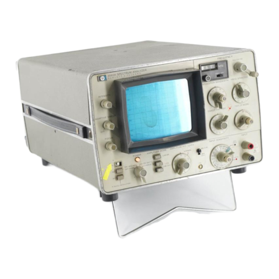
HP 3580A Operating And Service Manual (179 pages)
Spectrum analyzer
Brand:
HP
| Category:
Measuring Instruments
| Size: 31.72 MB
Table of Contents
Table of Contents
6
Description
10
Specifications
10
Options
10
Warranty Exceptions
10
Accessories Available
10
Instrument and Manual Identification
10
Front Panel
10
General Information
10
Grounding Requirements
14
Operating and Storage Temperature (Option 001)
14
Operating and Storage Temperature (Standard 3580A)
14
Environmental Requirements
14
Repackaging for Shipment
14
Power Cords and Receptacles
14
Initial Inspection
14
Introduction
14
Installation
14
Power Requirements
14
Controls, Connectors and Indicators
16
General Operating Information
16
Input Cable Requirements
16
Operating Features
16
About the Spectrum Analyzer
16
Introduction
16
Operating Instructions
16
Input Impedance
19
Input Constraints
19
Grounding
19
Ground Loops
20
Measurement Configurations
20
Power Line Ground Loop
20
Amplitude Modes
21
Absolute/Relative Measurements
21
Overload Indicator
22
Maximum Input Level
22
Amplitude Measurements (Linear Mode)
23
Dynamic Range
23
Sensitivity
23
Amplitude Section (Linear Mode)
24
Amplitude Measurements (Log Mode)
26
Amplitude Accuracy
26
Amplitude Section (Log Mode)
26
Internal Cal. Signal
27
Cal Signal
27
Noise Sidebands (1 Hz BW)
28
Two Signals in Passband
28
Bandwidth Setting
28
Frequency Setting
30
Frequency Span Setting
30
Amplitude Vs. Time
30
Frequency out of Range
31
Sweep Modes
31
Margin below 0 Hz
31
Log Sweep (300 Hz BW)
32
Sweep Time and Sweep Rate
33
External Triggering
34
Notch Filter (30 Hz BW)
34
Adaptive Sweep
35
Digitally-Stored Display
37
Recorder Outputs
37
Tracking Oscillator Output
38
Tracking Oscillator
38
Tracking Oscillator Input
39
Output
39
Option 002
40
Option 001
40
Basic Operating Procedures
41
Instrument Turn on
41
Frequency Calibration Procedure
42
Amplitude Calibration Procedure
42
Input Probe Compensation
43
Familiarization Exercise
44
Technique for Measuring Noise
45
Simplified Block Diagram
46
Amplitude Section
46
Simplified Block Diagram Description
46
Introduction
46
Theory of Operation
46
IF Amplifier
48
Linear Amplifier
48
Log Amplifier
49
Video Output
50
Frequency and Sweep Section
51
Adaptive Sweep Routine
53
Precision Monostable
58
Displaying a Stored Trace
60
Digital Storage and Display Sections
62
Digital Storage Section
63
Functional Description
63
Amplitude Section
63
Frequency and Sweep Section
63
Digital Storage Section (Store Mode)
63
Store Function ASM Chart
66
Store Button Released
68
Test Card
71
Frequency Tests
71
Maintenance
71
Performance Tests
71
Recommended Test Equipment
71
Introduction
71
Sweep Tests
73
Amplitude Tests
74
Bandwidth Tests
78
Dynamic Range Tests (Noise Tests)
79
Spurious Response Test
81
IF Feedthru and Zero Beat Response Tests
82
Input Impedance Tests
82
Output Tests
83
Balanced Input Tests
84
Adjustment Procedure
86
Test Point and Adjustment Locations
86
Power Supply Tests and Adjustments
86
Low Voltage Power Supply (A6)
86
Sweep Alignment and Dial Calibration
87
Display Adjustments
87
Line Generator Adjustments
89
Filter Alignment
90
Amplitude Calibration
91
Mixer Balance Adjustments
95
(According to MAX INPUT Indicator) FREQUENCY
96
(Fully CW)
96
Adaptive Sweep Marker Adjustment
96
Amplitude Mode
96
Amplitude Ref Level
96
Dbv/Lin - Dbm 600 Q
96
Frequency
96
Input Sensitivity
96
Reposition the Following Front Panel Controls
96
Those Controls Printed in BOLD Require a Change from the Previous Adjustments)
96
Db/DIV
102
Frequency
102
Input Sensitivity
102
Resolution Bandwidth
103
Introduction
106
Non-Listed Parts
106
Ordering Information
106
Proprietary Parts
106
Replaceable Parts
106
A2 Board VTO Troubleshooting
142
A3 Board Troubleshooting
142
General Troubleshooting Procedures
142
Introduction
142
Troubleshooting and Circuit Diagrams
142
Troubleshooting and Preventive Maintenance
142
A7 Board
145
High Voltage Power Supply
146
Battery Replacement (Option 001 Only)
147
CRT Replacement
147
Crystal Replacement
147
Cleaning and Lubricating Rotary Switches
148
Factory Selected Components
148
Schematic Diagrams
149
Introduction
166
Section VIII. BACKDATING
166
Advertisement
Advertisement
Related Products
HP 3575A
HP 3561a
HP 3562A
HP 3585A
HP 3400A
HP 333A
HP 334A
HP 3400B
HP Agilent 37717B SDH
HP 3720A
HP Categories
Desktop
Laptop
Server
Monitor
Switch
More HP Manuals
Login
Sign In
OR
Sign in with Facebook
Sign in with Google
Upload manual
Upload from disk
Upload from URL