Sign In
Upload
Manuals
Brands
horiba Manuals
Test Equipment
JOBIN YVON SYNAPSE
horiba JOBIN YVON SYNAPSE Manuals
Manuals and User Guides for horiba JOBIN YVON SYNAPSE. We have
1
horiba JOBIN YVON SYNAPSE manual available for free PDF download: User Manual
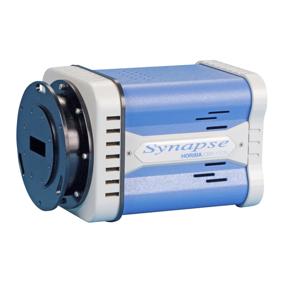
horiba JOBIN YVON SYNAPSE User Manual (116 pages)
CCD Detection System
Brand:
horiba
| Category:
Test Equipment
| Size: 2 MB
Table of Contents
Table of Contents
3
Disclaimer
7
Preface
9
Chapter 1: System Description and Specifications
11
Introduction
11
Table I. System Level Specifications for the Synapse CCD Detection System
12
Chapter 2: System Requirements
15
Input Power Requirements
15
Environmental Requirements
15
Ventilation Requirements
15
General Safety Requirements
16
Safety Symbols
17
Table II. Safety Symbols
17
Computer Requirements
19
Software
19
Hardware
19
General Maintenance Requirements
20
Cleaning the Detector Head
20
Cleaning the Dust Cover of the Power Supply Unit
20
Figure 1. Removable Dust Cover of Power Supply Unit
20
Chapter 3: Detector System Installation
21
Installation Overview
21
Unpacking and Equipment Inspection
22
Figure 2. Typical Synapse System Components
22
Table III. Individual Components for the Synapse
23
Installing Synerjy Application Software
24
Mounting Synapse to a Spectrograph
25
Figure 3. Flange Installation (Imaging Flange Pictured with Ihr320 Spectrograph)
25
Connecting Electrical Interface Cables
26
Figure 4. Typical Synapse Electrical Interconnect Scheme
27
Chapter 4: Initial Power-Up and Operation
29
Initial Power-Up
29
CCD Focus and Alignment on the Spectrograph
32
Preparing Focus and Alignment Mechanisms
32
Synapse Focus and Alignment
33
Figure 5. CCD Rotation and Adjustment Mechanisms
33
Figure 6. Example of a Focused and Aligned CCD
34
Modes of Data Acquisition
35
CCD Position
35
CCD Range
36
Triggering
36
Acquisition Mode Parameters
36
Chapter 5: Triggering
39
TTL Output Options
39
Shutter
39
Start Experiment
39
Ext Trigger Ready
39
Synchronized Triggering to an External Event
40
Figure 7. Timing Diagram for an Externally Triggered Single
41
Figure 8. Timing Diagram for an Externally Triggered Multi-Accumulation
42
Chapter 6: Auxiliary Analog Input
43
Normalization (Reference)
43
Figure 9. Typical Configuration for Normalization Using Synapse AUX in Port
43
Independent Data Acquisition
45
Figure 10. Typical Configuration for Independent Data Acq. Using Synapse AUX in Port
45
Configuring for Voltage and Current Modes
46
Chapter 7: Temperature Control
47
Chapter 8: Detector System Component Description
49
Synapse CCD Detector Head
49
Detector Head Cooling
49
Detector Head Chamber and Cooling Effectiveness
50
Detector Head Electrical Interfaces
50
Figure 11. Detector Head Electrical Interfaces
50
Shutter
51
Start Experiment
51
Ext Trigger Ready
52
Figure 12. External I C Connector Pin out (Viewed Looking at Rear of Detector)
53
Pixel Processing / Data Acquisition Modes of Operation
54
Gain Selections
55
Table IV. Synapse Gain Options Versus Sensor Offerings
55
System Noise
57
Figure 13. Typical Dark/Noise Scan for the Synapse in High Sensitivity Mode
58
Built-In-Test Diagnostic Capability
59
CCD Hardware Binning Control
59
CCD Exposure Control
59
Figure 14. Illustration of 2 X 2 Binning Operation on a 4 X 4 CCD Array
60
Synapse Power Supply Unit
61
Integrated te Power Supply
61
Integrated Power Shutter Drive Circuitry (Optional)
61
Power Supply Unit Electrical Interfaces
62
Figure 15. Power Supply Unit Electrical Interfaces
62
Software
63
Shutter
63
Table V. Shutter Models
64
Chapter 9: Powering down and Disassembly of the System
65
Power down Procedure
65
Disassembly of the Detection System
65
Chapter 10: Optimization and Troubleshooting
67
Optical Optimization
67
Spatial Optimization
67
Reducing the Number of Conversions
68
Environmental Noise Reduction
68
Cooling
69
Shutter
69
Power Interruption
69
Software Cannot Recognize Hardware Configuration
69
Unit Fails to Turn on
70
Appendix A: Dimensional Drawings
71
Figure 16. Synapse Detector Head
71
Figure 17. Distance from Focal Plane to CCD Chip
72
Figure 18. Synapse Power Supply Unit
73
Appendix B: Compliance Information
75
Declaration of Conformity
75
Supplementary Information
75
Table VI. Applicable CE Compliance Tests and Standards
76
Appendix C: Performing Routine Procedures with Synerjy
77
CCD Focus and Alignment on the Spectrograph
77
Triggering
81
Using the Auxiliary Analog Input Port
83
Normalization (Reference)
83
Independent Data Acquisition
84
Configuring for Voltage and Current Modes
85
Appendix D: Weee Recycling Passport
87
Table VII. Summary of Synapse Detection System Material Requiring Selective Treatment
87
Table VIII. Tools Required for Disassembly of the Synapse CCD Detection System
88
WEEE Product Marking
89
Figure 19. Synapse Detector Head Product Markings
90
Figure 20. Synapse Power Supply Unit Product Markings
90
General External View of Detector Head
91
Figure 21. General View of Synapse Detector Head Indicating Ext. Material for Recycling
91
Table IX. Breakdown of Synapse Recycling Components Viewed Externally
91
Dismantling of Detector Head
92
Figure 22. Illustration of the Dismantling Process for the Synapse Detector Head
92
Table X. Detector Head Disassembly Process
92
Notes for Dismantling Detector Head
93
Figure 23. Synapse Detector Head Depicting Location of Internal Material for Recycling
93
Table XI. Breakdown of Internal Detector Head Recycling
93
Complete Recycling Data of Detector Head
94
Table XII. Complete Recycling Data of Detector Head
94
General External View of Power Supply Unit
95
Figure 24. General View of Synapse Power Supply Unit Indicating Ext. Material for Recycling
95
Table XIII. Breakdown of Power Supply Unit Recycling Components Viewed Externally
95
Dismantling of Power Supply Unit
96
Figure 25. Illustration of the Dismantling Process for the Synapse Power Supply Unit
96
Table XIV. Power Supply Unit Disassembly Process
96
Notes for Dismantling Power Supply Unit
97
Figure 26. Synapse Power Supply Unit Depicting Location of Internal Material for Recycling
97
Table XV. Breakdown of Internal Power Supply Unit Recycling
97
Complete Recycling Data of Power Supply Unit
98
Table XVI. Complete Recycling Data of Power Supply Unit
98
Appendix E: Accessories
99
Table XVII. Available Accessories for Synapse
99
Service Policy
101
Return Authorization
102
Warranty
103
Index
115
Advertisement
Advertisement
Related Products
horiba 6582S-10C
horiba HP-8A
horiba Categories
Measuring Instruments
Security Sensors
Test Equipment
Monitor
Accessories
More horiba Manuals
Login
Sign In
OR
Sign in with Facebook
Sign in with Google
Upload manual
Upload from disk
Upload from URL