Sign In
Upload
Manuals
Brands
HORA Manuals
Controller
MC55/230
HORA MC55/230 Manuals
Manuals and User Guides for HORA MC55/230. We have
1
HORA MC55/230 manual available for free PDF download: Operating Manual
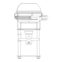
HORA MC55/230 Operating Manual (160 pages)
Linear actuators
Brand:
HORA
| Category:
Controller
| Size: 12 MB
Table of Contents
Section 1
5
Table of Contents
5
1 Safety
6
Proper Use
6
Information for the Operator
6
Personnel
7
Prior to Starting Work
7
During Operation
7
Working Environment
7
2 Product Specification
8
Component Parts
8
Operating Modes
9
Continuous Mode MC55Y
9
Three-Point Mode MC55/24, MC55/230
9
Functions
9
Binary Signal / Frost Protection Function MC55Y
9
Blockage Detection
10
Wire Break Detection MC55Y
10
Actuating Time
10
Manual Operation
10
Technical Data
11
Type Plate
12
3 Transportation & Storage
12
4 Assembly
13
Checking the Scope of Delivery
13
Preparing Assembly
13
Mounting the Linear Actuator on the Valve
14
Assembling/Disassembling the Cover
15
Electrical Connection
16
Controller Independent Circuit MC55Y
18
Remove Push-Fit PCB and Transformer
19
Mc55/230
19
5 Commissioning
20
Operating Parameters and Jumper Settings
21
Setting the Input Signal for MC55Y
21
Setting the Actuating Time
21
Setting the Actuating Direction
22
Setting the Limit Position for MC55Y
23
Commissioning
23
6 Operation
24
Changing between Manual and Automatic Mode
24
7 Maintenance, Care and Repairs
25
8 Spare Parts
25
9 Decommissioning and Disposal
25
10 Removal of Faults
25
How to Remedy Faults
25
Check List for Breakdown
26
Section 2
29
1 Safety
30
Proper Use
30
Information for the Operator
30
Personnel
31
Prior to Starting Work
31
During Operation
31
Working Environment
31
2 Product Specification
32
Component Parts
32
Accessories
33
Operating Modes
33
Continuous Mode
33
Three-Point Mode
34
Functions
34
Binary Signal / Frost Protection Function
34
Blockage Detection
34
Wire Break Detection
34
Actuating Time
35
Hysteresis
35
Manual Mode and Response Signal
35
Auto Test
35
Auto Pause
35
Potential-Free Limit Switch (Accessory)
35
Technical Data
36
Type Plate
37
3 Transportation & Storage
37
4 Assembly
38
Checking the Scope of Delivery
38
Preparing Assembly
38
Mounting the Linear Actuator on the Valve
39
Assembling/Disassembling the Cover
40
Electrical Connection
41
Controller Independent Circuit
43
Removing the PCB Cover
44
Fitting Accessories
45
Fitting a PCB for a Path Switch
45
Fitting the PCB for the Ma Output Signal
46
5 Commissioning
48
Operating Parameters and Encoding Switch Settings
49
Setting the Input Signal
49
Setting the Actuating Time
49
Setting the Hysteresis
50
Setting the Actuating Direction
50
Setting Auto Test and Auto Pause
50
Setting the Limit Position
51
Setting a Potential-Free Path Switch
51
Initialising the Path Measuring System
53
Commissioning
54
6 Operation
55
Changing between Manual and Automatic Mode
55
LED Display
56
7 Maintenance, Care and Repairs
56
8 Spare Parts
56
9 Decommissioning and Disposal
57
10 Removal of Faults
57
How to Remedy Faults
57
Check List for Breakdown
58
Section 3
61
1 Safety
62
Proper Use
62
Information for the Operator
62
Personnel
63
Prior to Starting Work
63
During Operation
63
Working Environment
63
2 Product Specification
64
Component Parts
64
Accessories
65
Operating Modes
65
Continuous Mode
65
Three-Point Mode
66
Functions
66
Binary Signal / Frost Protection Function
66
Blockage Detection
66
Wire Break Detection
66
Actuating Time
67
Hysteresis
67
Manual Mode and Response Signal
67
Auto Test
67
Auto Pause
67
Potential-Free Limit Switch (Accessory)
67
Technical Data
68
Type Plate
69
3 Transportation & Storage
69
4 Assembly
70
Checking the Scope of Delivery
70
Preparing Assembly
70
Mounting the Linear Actuator on the Valve
71
Assembling/Disassembling the Cover
74
Electrical Connection
75
Controller Independent Circuit
77
Removing the PCB Cover
78
Fitting Accessories
79
Fitting a PCB for a Path Switch
79
Fitting the PCB for the Ma Output Signal
80
5 Commissioning
82
Operating Parameters and Encoding Switch Settings
83
Setting the Input Signal
83
Setting the Actuating Time
83
Setting the Hysteresis
84
Setting the Actuating Direction
84
Setting Auto Test and Auto Pause
84
Setting the Limit Position
85
Setting a Potential-Free Path Switch
85
Initialising the Path Measuring System
87
Commissioning
88
6 Operation
89
Changing between Manual and Automatic Mode
89
LED Display
90
7 Maintenance, Care and Repairs
90
8 Spare Parts
90
9 Decommissioning and Disposal
91
10 Removal of Faults
91
How to Remedy Faults
91
Check List for Breakdown
92
Section 4
95
1 Safety
96
Proper Use
96
Information for the Operator
96
Personnel
97
Prior to Starting Work
97
During Operation
97
Working Environment
97
2 Product Specification
98
Component Parts
98
Accessories
99
Operating Modes
99
Continuous Mode
99
Three-Point Mode
100
Functions
100
Binary Signal / Frost Protection Function
100
Blockage Detection
100
Wire Break Detection
100
Actuating Time
101
Hysteresis
101
Manual Mode and Response Signal
101
Auto Test
101
Auto Pause
101
Potential-Free Limit Switch (Accessory)
101
Technical Data
102
Type Plate
103
3 Transportation & Storage
103
4 Assembly
104
Checking the Scope of Delivery
104
Preparing Assembly
104
Mounting the Linear Actuator on the Valve
105
Assembling/Disassembling the Cover
107
Electrical Connection
108
Controller Independent Circuit
110
Removing the PCB Cover
111
Fitting Accessories
112
Fitting a PCB for a Path Switch
112
Fitting the PCB for the Ma Output Signal
113
5 Commissioning
115
Operating Parameters and Encoding Switch Settings
116
Setting the Input Signal
116
Setting the Hysteresis
116
Setting the Actuating Direction
116
Setting Auto Test and Auto Pause
117
Setting the Limit Position
118
Setting a Potential-Free Path Switch
118
Initialising the Path Measuring System
120
Commissioning
122
6 Operation
122
Changing between Manual and Automatic Mode
122
LED Display
123
7 Maintenance, Care and Repairs
123
8 Spare Parts
123
9 Decommissioning and Disposal
124
10 Removal of Faults
124
How to Remedy Faults
124
Check List for Breakdown
125
Section 5
131
1 Safety
132
Proper Use
132
Information for the Operator
132
Personnel
133
Prior to Starting Work
133
During Operation
133
Working Environment
133
2 Product Specification
134
Components
134
Accessories
135
Operating Modes
135
Continuous Mode
135
Three-Point Mode
136
Functions
136
Binary Signal / Frost Protection Function
136
Lock Detection
136
Internal Temperature Monitoring
136
Open-Circuit Detection
137
Set Time
137
Hysteresis
137
Manual Mode and Feedback Signal
137
Autotest
138
Autopause
138
Potential-Free Way-Switch (Optional Extra)
138
Technical Data
138
Ratingplate
139
3 Transport and Storage
139
4 Assembly
140
Check the Scope of Supply
140
Prepare for Installation
140
Mount Linear Actuator on Valve
141
Fit/Remove Cover
142
Connect the Electrics
143
Control-Independent Switching
145
Remove Printed Circuit Board Cover
146
Optional Extras Installation
146
Way-Switch Printed Circuit Board Installation
147
Fit the Printed Circuit Board for Ma Output Signal
148
5 Commissioning
150
Operating Parameters and Coding Switch Positions
150
Set Input Signal
151
Set Actuating Time
151
Set Hysteresis
152
Set Actuating Direction
152
Set Autotest and Autopause
152
Set Limit Position
153
Set Potential-Free Way-Switch
153
Initialise the Path-Measuring System
155
Commissioning
157
6 Operation
157
Switching between Manual and Automatic Modes
157
LED Display
158
7 Maintenance, Care and Repairs
158
8 Spare Parts
158
9 Shutdown and Disposal
159
10 Troubleshooting
159
Operating Faults Checklist
160
Advertisement
Advertisement
Related Products
HORA MC500/24
HORA MC503/24
HORA MC500/230
HORA MC503/230
HORA MC55/24
HORA MC55Y
HORA MC250/24
HORA MC253/230
HORA MC250/230
HORA MC253/24
HORA Categories
Controller
More HORA Manuals
Login
Sign In
OR
Sign in with Facebook
Sign in with Google
Upload manual
Upload from disk
Upload from URL