Sign In
Upload
Manuals
Brands
Honeywell Manuals
Measuring Instruments
ACM 150
Honeywell ACM 150 Gas Monitoring System Manuals
Manuals and User Guides for Honeywell ACM 150 Gas Monitoring System. We have
2
Honeywell ACM 150 Gas Monitoring System manuals available for free PDF download: User Manual, Manual To Installation, Operation, And Maintenance
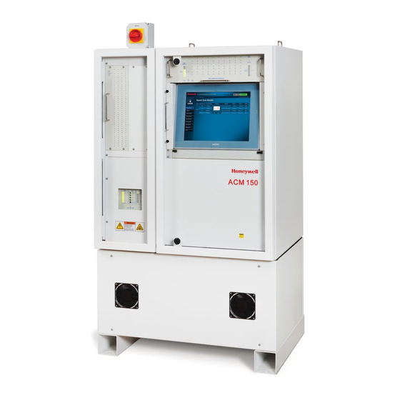
Honeywell ACM 150 User Manual (176 pages)
Air Composition Monitor
Brand:
Honeywell
| Category:
Measuring Instruments
| Size: 11 MB
Table of Contents
Table of Contents
2
Instruction
11
Contacts
11
ACM 150 Standard Warranty
13
Safety
14
Safe and Proper Operation of the ACM 150 Monitor
14
End User Responsibilities
14
Safety Notices and Terms
14
Danger/Warning/Caution/Note
14
Levels of ACM 150 User
15
All Users
15
Authorized Users
15
Trained Technician
16
Risk Analysis
16
Chemical Safety
17
Process Compatibility
17
Electrical Safety
18
Hazardous Energy Isolation
18
Compressed Air Isolation
19
Nitrogen Isolation
19
Emissions
19
Ergonomics
19
Flammability
20
Potential Key Failure Points and Trouble Spots
20
Potentially Hazardous Maintenance Activities
20
Environmental Issues
20
Exhaust Treatment
21
ACM 150 Labels
21
Security Guide
21
Figure 1. ACM 150 Outside Labels
22
Figure 2. ACM 150 Inside Labels
23
Technical Description and Theory of Operation
24
Overview of the ACM 150 Monitor
24
ACM 150 Arrangement and Assemblies
24
General Arrangement
24
Figure 3. General Arrangement
25
Main Power Switch
26
Sample Valve Manifolds
26
Figure 4. Main Power Switch
26
Figure 5. 10 Sample Valve Manifold
26
Sample Valve Control Panel
27
Figure 6. Sample Inlets 40-Point
27
Figure 7. Sample Valve Control Panel
27
Control Panel Status
28
Figure 8. Control Panel Status Leds
28
Cycle Valves
29
Figure 9. Cycle Valve Assembly
29
Cycle Valve Control Panel
30
Figure 10. Cycle Valve Control Panel
31
Pump Assemblies
32
Figure 11. Venturi Pump Assembly
32
Figure 12. Mechanical Pump Assembly
33
FTIR Bench & Gas Cells
34
Figure 13. FTIR Bench Assembly
34
Touchscreen Computer Assembly
35
Figure 14. Touchscreen Overview and with Events
36
Relay Outputs
37
Figure 15. Relay Output Board
38
Figure 16. Relay Schematic
39
Relay Output Control Panel
40
Figure 17. Typical Relay Layout
40
Figure 18. Relay Control Panel
41
Electrical Layout
42
Power Distribution Panel
42
Figure 19. Power Distribution Panel
42
Interconnecting Cables
43
Air Sampling System
43
ACM 150 Flow Cycles
43
Bypass and Order of Scan
44
Background Cycle
44
Valve Switching and Timing
45
Table 1. Cycle Timing and Readings
45
CDA Panel
46
Figure 20. CDA Panel
46
Other Sampling Components
47
Figure 21. Venturi Supply (Option)
47
Optional Capabilities
48
Sample Points
48
Automatic Line Leak Test
48
ACM 150 Operating Principle
49
Basic Operation
49
Wavenumber Precision
49
Absorbance and Gas Concentration
49
Permanent Calibration
50
Analytical Methods
51
ZPD Values (ZPD Energy and ZPD Position)
52
Installation Environment
53
Space Requirement
53
Temperature and Protection
53
Electrical Area
53
Utility Requirements
53
Vacuum Sampling System
54
Available Outputs
54
Data Interface and Protocol
54
Installation
55
Receipt and Unpacking
55
Figure 22. Floor Mounting Locations
55
Electrical Power
56
Line Power, 115 / 230 Volts AC
56
Figure 23. Ergonomic
56
Emergency Power-Off (EPO) Option
57
Lockout/Tagout (LOTO) Disconnect
57
Figure 24. Main Power Switch and Supply Connections
57
International Line Power
58
Isolation Transformer
58
Maintaining AC Power
58
Utility Gases and Exhaust Piping
59
Nitrogen Supply
59
Air Supply
59
Exhaust
60
Figure 25. Nitrogen, CDA, and Exhaust Connections
60
Sample Tubing and Filters
61
Tubing Material
61
Tubing Run Lengths
61
ACM 150 Tube Connection Points
61
Sample Area Connections
62
Figure 26. ACM 150 Tube Connection Points
62
Filters, Check Valves, and Probes
63
Wiring the Outputs
64
Access Plates
64
Relay Output Wiring
64
Figure 27. Output Wiring Access Panels
64
Relay Terminals and Activation Options
65
Figure 28. Relay Output Wiring
66
FTIR Bench Installation
67
Data Interface
67
Remote Computers
67
Networks
67
Figure 29. Clamps on the FTIR Bench
67
Interfacing to PLC
68
Ethernet Interface
68
Installation Drawings
69
Figure 30. ACM 150 Installation Diagram 1
69
Figure 31. ACM 150 Installation Diagram 2
70
Operation
72
Safe and Proper Operation of the ACM 150 Monitor
72
ACM 150 Operating Safety
72
Computer Information
73
ACM 150 Touchscreen and Keyboard
73
Remote Computer Access
73
Status and Scan Results
73
Area Scanning
73
Background
73
Status Bar
73
Figure 32. Status Bar
73
Figure 33. Alarm Service Events
73
Overview and Recent Scan Results
74
Figure 34. Alarms and Service Status Details
74
Figure 35. Status Bar (Manual Mode)
74
Figure 36. Normal Scan
75
Figure 37. Recent Scan
76
Changing the Mode of Operation
77
Figure 38. Menu Tree
77
Table 2: Menu Access Levels
77
Alarm 1/Alarm Two Incidents and Actions
78
Alarm 1/Alarm 2 Event Log
78
Figure 39. Alarm Event History
78
Relay Activation
79
Programming Relays
79
Figure 40. Export Events
79
Action Plan
80
Lock-On Mode and Demand Scan Mode
80
Lock-On Mode
80
Figure 41. Select a Point Lock-On Scan
81
Figure 42. Lock-On Button
81
Demand Scan Mode
82
Figure 43. Lock-On Scan Spectrum
82
Figure 44. Demand Scan
83
Figure 45. Demand Scan Spectrum
84
Archived Spectrum and Trends
85
Figure 46. Archived Views
85
Archived Spectrum View
86
Figure 47. Archived Spectrum
86
Trend Graphs
87
Figure 48. Gases Concentration in a Scanned Point
87
Time-Weighted Average
88
ACM 150 Checklist and Incident Plan
88
Figure 49. Trend Graph Display
88
Plan for ACM 150 Incidents
89
Screening Data
89
Signal-To-Noise Ratio
91
Maintenance Gas
91
Spectrum Overlay
92
Figure 50. Spectrum Overlay
92
Figure 51. Move to Spectrum Overlay from Recent Scan
93
Information
94
Figure 52. ACM 150 Product Information
94
Settings Menu
95
Accessing the Settings Menu
95
ACM Configuration
95
Settings - General Configuration
95
Date and Time Configuration
95
Network Configuration
95
Settings - Account Manager
95
Figure 53. Account Manager
96
Settings - Point Configuration
97
Figure 54. Point Configuration
97
Figure 55. Edit Point Configuration
98
Settings - Order of Scan
99
Reviewing the Order of Scan
99
Figure 56. Order of Scan
99
Configuration Key
100
Figure 57. Enabled Point List
100
Reviewing and Changing the Order of Scan
101
Figure 58. Review the Order of Scan
101
Figure 59. Editing the Order of Scan
102
Table 3: Scan Points Configuration
102
Composite Points
103
Figure 60. Composite Points
103
Settings - Method Manager
104
Figure 61. Method Manager
104
Settings - Relay Configuration
105
Reviewing the Programmable Relays
105
Figure 62. View Relay Configuration
105
Selecting the Relay Program
106
Figure 63. Relay Configuration
106
Table 4. Relay Programming Steps
106
Settings - Import/Export Configuration
107
Figure 64. Selecting Relay Gases
107
Figure 65. Export/Import Configuration
108
Shutdown Procedure
109
Emergency Shutdown
109
Planned Shutdown
109
Line Power
109
Utility Gases
109
Figure 66. Main Power Switch
109
Internal Disconnects
110
Maintenance
110
Lockout / Tagout Procedure
110
Acm 150
110
External
110
Decontamination / Decommissioning Procedures
111
Purpose
111
Procedures
111
Inspection and Service Schedule
111
Monthly Service
112
Quarterly Inspection
112
Annual PM Services
112
Table 5: Service Events
112
Two-Year Service
113
Five-Year Service
113
Contract Services
113
Service Operations
114
Archives Menu
114
Spectrum
114
Figure 67. Archives Spectrum Data
114
Gas Conc. Trend
115
SNR Trend
115
ZPD Trend
115
Figure 68. ZPD Trend
115
Download
116
Figure 69. Download Exporting Data
116
Diagnostics Menu
117
Figure 70. Status Bar
117
Table 6: Diagnostics Menu
117
Background Scan
118
Figure 71. Acquire Background
118
View Cycle
119
Figure 72. View Valve Cycles
119
View Spectrum
120
Hardware Service
120
Figure 73. View Spectrums
120
Figure 74. Cycle Valve Test (Dual Pump, Line Leak Option)
121
Figure 75. Cycle Valve Test (Venturi Pump, Line Leak Option)
121
Figure 76. Sample Valves Manual Control
122
Figure 77. Relays Manual Control
123
Figure 78. Kinked Tube Test
124
Software Service
125
Figure 79. Memory Maintenance
125
Figure 80. Alarm Simulation
126
Service Inspections and Procedures
127
Preparation for Servicing
127
Figure 81. Fault Simulation
127
Servicing the Filters
128
Visual Inspection
129
Servicing the Pumps
129
Servicing the Valves
130
Evaluating the FTIR Optical Path
130
Servicing the Gas Cell
132
Servicing the Line Leak Test
133
Servicing the Desiccant Module
133
Manual Tests and Evaluations
133
Cycle Valve Tests
133
Sample Valve Tests
134
Line Leak Tests (Optional)
136
Evaluating/Resolving the ZPD Position
137
Evaluating/Resolving Spectral Balance
137
Figure 82. Normal Background Spectrum
137
Figure 83. Abnormal Background Spectrum
137
Service and Setup Instructions
138
Solenoid Valves
138
Backup Vacuum Pump
139
Figure 84. Backup Vacuum Pump Diagram
140
Line Leak Test Setup Procedure
141
Table 7: Backup Vacuum Pump Parts List
141
Configuration Problems
142
Troubleshooting
143
Identifying Problems
143
Utilizing Relay Outputs
143
Utilizing Daily Inspections
143
Resolving Problems
144
Table 8: Service Request Messages
144
Recommended Action
144
Backup Log Files
145
PPC Log Files
145
SBC Log Files
145
Appendix
146
Appendix A. Master Parts List
146
Appendix B. Event List
149
Appendix C. MODBUS Register Map
153
Appendix D. Gas List
158
Appendix E. Technical Specifications
159
Performance Specifications
159
Facilities Requirements
159
Appendix F. MSDS
161
Kbr MSDS
161
Znse MSDS
166
Appendix G. Glossary
174
Access Codes
174
Ehs
174
Ert
174
Ftir
174
Lan
174
Lockout/Tagout
174
Psia
174
Psig
175
Ppm
175
Tlv
175
Twa
175
Ppc
175
Sbc
175
Qnx
175
Advertisement
Honeywell ACM 150 Manual To Installation, Operation, And Maintenance (156 pages)
Air Composition Monitor
Brand:
Honeywell
| Category:
Measuring Instruments
| Size: 6 MB
Table of Contents
Table of Contents
3
Introduction
4
Contacts
5
Warranty
6
Safety
7
Technical Description and Theory of Operation
17
Air Sampling System
34
ACM 150 Operating Principle
40
Installation Environment
43
Installation Drawings
58
Operation
61
Setup Menus
81
Shutdown Procedure
98
Technical Specifications
100
Maintenance
102
Manual Tests and Evaluations
126
Troubleshooting
135
Appendix A: Kbr MSDS
137
Appendix B: Znse MSDS
142
Appendix C: Glossary
150
Advertisement
Related Products
Honeywell ACM 150G2
Honeywell APT4000PH
Honeywell AS302P
Honeywell NOTIFIER AM-8200
Honeywell NOTIFIER AM-8200-BB
Honeywell AD1200
Honeywell AD1200-CT
Honeywell AC-250NXS
Honeywell Notifier ACM-8R
Honeywell ACS4C3
Honeywell Categories
Thermostat
Controller
Control Unit
Security Camera
Security System
More Honeywell Manuals
Login
Sign In
OR
Sign in with Facebook
Sign in with Google
Upload manual
Upload from disk
Upload from URL