Sign In
Upload
Manuals
Brands
Holtek Manuals
Transceiver
BC66F5652
Holtek BC66F5652 Manuals
Manuals and User Guides for Holtek BC66F5652. We have
1
Holtek BC66F5652 manual available for free PDF download: Manual
Holtek BC66F5652 Manual (242 pages)
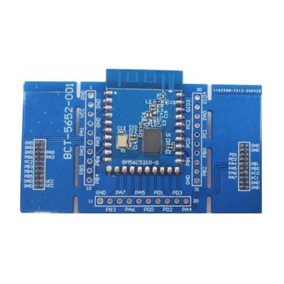
RF 2.4GHz A/D Flash MCU
Brand:
Holtek
| Category:
Transceiver
| Size: 3 MB
Table of Contents
Table of Contents
2
Features
7
CPU Features
7
Peripheral Features
7
RF Transceiver Features
8
General Description
8
Block Diagram
9
Pin Assignment
10
Pin Description
11
Interconnection Signal Description
15
Absolute Maximum Ratings
15
D.C. Characteristics
16
Operating Voltage Characteristics
16
Operating Current Characteristics
16
Standby Current Characteristics
17
A.C. Characteristics
17
High Speed Internal Oscillator - HIRC
17
External High Speed Crystal/Ceramic Oscillator - HXT
18
Low Speed Internal Oscillator Characteristics - LIRC
18
External Low Speed Crystal Oscillator Characteristics - LXT
18
Operating Frequency Characteristic Curves
18
System Start up Time Characteristics
19
Input/Output Characteristics
20
Memory Characteristics
20
A/D Converter Electrical Characteristics
21
LVD/LVR Electrical Characteristics
22
Reference Voltage Electrical Characteristics
22
Comparator Electrical Characteristics
23
Software Controlled LCD Driver Electrical Characteristics
23
RF Transceiver Characteristics
24
D.C. Characteristics
24
Power-On Reset Characteristics
25
System Architecture
26
Clocking and Pipelining
26
Program Counter
27
Stack
27
Arithmetic and Logic Unit - ALU
28
Flash Program Memory
29
Structure
29
Special Vectors
29
Look-Up Table
29
In Circuit Programming - ICP
31
On-Chip Debug Support - OCDS
31
In Application Programming - IAP
32
Data Memory
46
Structure
46
Data Memory Addressing
47
General Purpose Data Memory
47
Special Purpose Data Memory
47
Special Function Register Description
49
Indirect Addressing Registers - IAR0, IAR1, IAR2
49
Memory Pointers - MP0, MP1L, MP1H, MP2L, MP2H
49
Accumulator - ACC
50
Program Counter Low Register - PCL
51
Look-Up Table Registers - TBLP, TBHP, TBLH
51
Status Register - STATUS
51
EEPROM Data Memory
53
EEPROM Data Memory Structure
53
EEPROM Registers
53
Read Operation from the EEPROM
55
Page Erase Operation to the EEPROM
55
Write Operation to the EEPROM
56
Oscillators
61
Oscillator Overview
61
System Clock Configurations
61
External Crystal/Ceramic Oscillator - HXT
62
Internal High Speed Internal RC Oscillator - HIRC
63
External 32.768Khz Crystal Oscillator - LXT
63
Internal 32Khz Oscillator - LIRC
64
Operating Modes and System Clocks
64
System Clocks
64
System Operation Modes
65
Control Registers
66
Operating Mode Switching
69
Standby Current Considerations
72
Wake-Up
72
Programming Considerations
73
Watchdog Timer
73
Watchdog Timer Clock Source
73
Watchdog Timer Control Register
73
Watchdog Timer Operation
74
Reset and Initialisation
75
Reset Functions
75
Reset Initial Conditions
79
Input/Output Ports
82
Pull-High Resistors
82
Port a Wake-Up
83
I/O Port Control Registers
84
I/O Port Source Current Control
84
Pin-Shared Functions
85
I/O Pin Structures
90
Programming Considerations
90
Timer Modules - TM
91
Introduction
91
TM Operation
91
TM Clock Source
91
TM Interrupts
92
TM External Pins
92
Programming Considerations
93
Compact Type TM - CTM
94
Compact Type TM Operation
94
Compact Type TM Register Description
95
Compact Type TM Operating Modes
98
Standard Type TM - STM
104
Standard Type TM Operation
104
Standard Type TM Register Description
104
Standard Type TM Operation Modes
108
Periodic Type TM - PTM
118
Periodic Type TM Operation
118
Periodic Type TM Register Description
118
Periodic Type TM Operation Modes
122
Analog to Digital Converter
131
A/D Converter Overview
131
A/D Converter Register Description
132
A/D Converter Reference Voltage
135
A/D Converter Input Signals
136
A/D Converter Operation
136
A/D Conversion Rate and Timing Diagram
137
Summary of A/D Conversion Steps
138
Programming Considerations
139
A/D Conversion Function
139
A/D Converter Programming Examples
140
Comparator
141
Comparator Operation
141
Comparator Registers
141
Comparator Interrupt
142
Programming Considerations
142
Serial Interface Module - SIM
143
SPI Interface
143
I 2 C Interface
150
UART Interface
160
UART External Pins
160
UART Data Transfer Scheme
161
UART Status and Control Registers
161
Baud Rate Generator
166
UART Setup and Control
167
UART Transmitter
168
UART Receiver
169
Managing Receiver Errors
171
UART Interrupt Structure
172
UART Power down and Wake-Up
173
SCOM/SSEG Function for LCD
174
LCD Operation
174
LCD Control Registers
175
Low Voltage Detector - LVD
178
LVD Register
178
LVD Operation
178
Interrupts
179
Interrupt Registers
179
Interrupt Operation
184
External Interrupt
185
Comparator Interrupt
186
Multi-Function Interrupts
186
A/D Converter Interrupt
186
Time Base Interrupts
186
TM Interrupts
188
Serial Interface Module Interrupt
188
UART Transfer Interrupt
189
LVD Interrupt
189
EEPROM Interrupt
189
Interrupt Wake-Up Function
189
Programming Considerations
190
Configuration Options
190
RF Transceiver
191
Memory Mapping
191
Special Function Register
192
Bank 2 Control Register
205
Functional Description
206
State Machine
208
Abbreviation
216
Application Circuits
217
Instruction Set
218
Introduction
218
Instruction Timing
218
Moving and Transferring Data
218
Arithmetic Operations
218
Logical and Rotate Operation
219
Branches and Control Transfer
219
Bit Operations
219
Other Operations
219
Instruction Set Summary
220
Extended Instruction Set
222
Instruction Definition
224
Extended Instruction Definition
233
Package Information
240
SAW Type 46-Pin QFN (6.5Mm×4.5Mm×0.75Mm) Outline Dimensions
241
Advertisement
Advertisement
Related Products
Holtek BC66F2332-1
Holtek BC45B4523
Holtek BC68F2130
Holtek BC68F2140
Holtek BC68F2150
Holtek BC68F3132
Holtek BC7601
Holtek BC7602
Holtek BC32F7611
HOLTEK BS67F370
Holtek Categories
Microcontrollers
Storage
Computer Hardware
Motherboard
Control Unit
More Holtek Manuals
Login
Sign In
OR
Sign in with Facebook
Sign in with Google
Upload manual
Upload from disk
Upload from URL