Sign In
Upload
Manuals
Brands
Hologic Manuals
Medical Equipment
DISCOVERY C
User Manuals: Hologic DISCOVERY C Bone Densitometer
Manuals and User Guides for Hologic DISCOVERY C Bone Densitometer. We have
1
Hologic DISCOVERY C Bone Densitometer manual available for free PDF download: Technical Manual
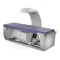
Hologic DISCOVERY C Technical Manual (274 pages)
FAN BEAM X-RAY BONE DENSITOMETER
Brand:
Hologic
| Category:
Medical Equipment
| Size: 4 MB
Table of Contents
Table of Contents
3
Chapter 1 - INTRODUCTION
9
System Overview
9
X-Ray Scanning Principles
10
Functional Overview
12
Product Specifications
18
Exam Mode(S) Performance
20
Duty Cycle
21
Leakage Technique Factors
21
Minimum Beam Filtration
21
Measured Half Value Layer (HVL) at Different Operating Potentials
21
Line Voltage and Maximum Line Current
21
Technique Factors for Maximum Line Current
21
Maximum Deviation
22
Measurement Criteria for Technique Factors
22
Functional Description
23
Computer
23
PCI Communications Controller Board
23
Interface Connections
23
Distribution Board
25
Power
25
Interface Connections
26
Motor Controller Board
27
Power
27
Interface Connections
28
TZ Drive Board (a and SL Only)
28
Service Switches
29
Power
29
Interface Connections
30
Control Panel Controller Board
32
Power
32
Interface Connections
32
C-Arm Interface Board
34
Continuity Daisy Chain
35
Power
35
Interface Connections
35
X-Ray Controller Assembly (P/N 010-1273)
38
Interface
38
X-Ray Controller Board
40
X-Ray Source Unit
41
Data Acquisition System (C, W, and SL)
42
Solid State Detector
42
Integrator/Multiplexor Subsection
42
Analog to Digital Board
43
Power
43
Interface Connections
43
Data Acquisition System (a Model Only)
45
Solid State Detector
45
Power
45
Interface Connections
45
Integrator/Multiplexor Board
46
Power
47
Interface Connections
47
Analog to Digital Board (a Model Only)
49
Power
49
Interface Connections
49
Torroid Power Module and DIN Rail
51
Chapter 3 - INSTALLATION
53
Pre-Installation Requirements
53
Required Tools
53
Required Documentation
53
Room and Doorway Size
54
Arrange for Help
58
Uncrate and Move to Destination
58
Inspect for Shipping Damage
58
Uncrate Unit
59
Take Inventory
60
Measure Path to Final Destination
60
Remove Tabletop (if Necessary)
61
Remove Discovery a or SL Lower C-Arm Assembly (if Necessary)
62
Prepare the Tabletop for Moving (A, W,Wi)
64
Move Unit to Destination
64
Set up the Unit
68
Install the System
70
Install Cables
70
Check Power Line Voltage
75
Install Computer
76
Start QDR Software in Service Mode
76
Check Table Alignment
77
Perform C-Arm Parallelism Adjustment (a and SL Systems Only)
79
Calibrate and Test the System
80
Check Tube Kv Peak Potential
80
Check Tube Current
82
Adjust Belt Tension
84
Calibrate Motors
85
X-Ray Beam Alignment
99
Calibrate Aperture (Cannot be Run on CI and Wi Models)
105
Check Laser Positioning Offset
106
A/D Gain Control Adjustment
106
Check and Verify the A/D Gain
106
Adjust the A/D Gain
107
Perform Detector Flattening
107
Perform Lateral Alignment Test (a and SL)
108
Check HVPS/S (Tank) for Radiation Leakage
110
Calibrate for Area, BMD and BMC
112
Scan Thickness Measurement & Calibration (C and W)
113
Scan Thickness Measurement & Calibration (a and SL)
113
Calibration of Area and BMC, for Array Scan Modes
114
RECALYZE and Add Array AP Scans to the QC Database
115
Install Software Options
116
Test Scan Modes
116
Finish Assembling Unit
118
Measure X-Ray Dose to Patient
118
Measure X-Ray Scatter from Phantom
119
Perform QC
119
Run Reproducibility Test
119
Instruments Using Body Composition Analysis (BCA)
121
Instruments Using BMD Whole Body Analysis
122
The Radiation Measurement Report
122
Alignment and Calibration
123
Check Table Alignment
123
Align the Table
123
Front to Back T-Rail and Table Edge/Rail Gap Adjustment
125
C-Arm Parallelism Adjustment
125
X-Ray Beam Alignment
126
Aperture Calibration
131
Motor Calibration
132
Laser Positioning Offset Adjustment
148
A/D Gain Control Adjustment
148
Check and Verify the A/D Gain
149
Adjust the A/D Gain
149
Filter Drum Encoder Alignment
150
Detector Flattening
151
Lateral Alignment Test (QDR 4500A and SL)
152
Instruments Using Body Composition Analysis (BCA)
155
Instruments Using BMD Whole Body Analysis
155
Check Phantom Values
156
Area, BMD, and BMC Calibration
156
Scan Thickness Measurement & Calibration (C and W)
157
Scan Thickness Measurement & Calibration (a and SL)
158
Calibration of Area and BMC, for Array Scan Modes
159
RECALYZE and Add Array AP Scans to the QC Database
160
Remove and Replace Procedures
167
Recommended Tools
167
Electronics Tray FRUS
167
Electronics Tray Printed Circuit Boards
168
C-Arm y Motor or Gearcase
169
C-Arm y Encoder
170
Control Panel (All Models)
171
Pcbs under Right-Side of the Table
171
Pedestal
178
The Linear Rotary String (Encoder)
180
Lower C-Arm FRUS
182
C-Arm Interface Board
183
X-Ray Controller Assembly
184
Filter Drum Assembly
184
Tank Assembly
185
Arm R FRUS (a and SL Only)
187
Motor Controller Board
189
Arm R Belt
189
Arm R Motor, Gearcase, Encoder or Encoder Belt
190
Gas Spring
191
Upper C-Arm FRUS
191
Detector Assembly A, SL, W, C Systems
192
Detector Assembly C1 and Wi Systems
193
Laser Assembly
195
Analog to Digital Converter Board (a Model Only)
196
Aperture Assembly FRUS
197
Aperture Stepper Motor
197
Aperture Motor PCB
198
Aperture Position Belt
198
Rotary Potentiometer
199
Drum Assembly FRUS
200
Drum Encoder PCB
200
Drum Belts
202
Stepper Motor Assembly
203
Drum Bearings
203
Replacing EMI Cables
206
FRU Lists
207
Chapter 6 - FAULT ISOLATION
213
Before Starting
213
Software Configuration
213
Hardware Configuration
213
Power Problems
213
Motion Problems
214
Control Panel Problems
217
Display Problems
217
Vertical Stripe
217
Horizontal Stripe
218
Noise
219
No Display
219
Targeting/Laser Problems
220
Data Communications Problems
220
Area/Bmd/Bmc/CV Specification Problems
221
X-Ray Problems
221
No X-Rays
221
X-Ray Alignment Problems
221
X-Ray Beam Does Not Align Properly
221
System Fails X-Ray Beam Alignment Verification
222
Detector Flattening Problems
222
System Consistently Fails the Detector Flattening Procedure
222
Laser Problems
223
Oil Leakage
224
The Torque Specifications
224
Tank Top Cover Components and Screw Location
224
Tightening the Lexan Cup Screws
225
Tightening the Bladder Gasket Screws
225
Tightening the Transformer Seal Screws
226
Tightening the Tank Cover Gasket Screws
226
Miscellaneous Problems
227
Preventive Maintenance
229
Customer Preventive Maintenance
229
Field Service Preventive Maintenance
229
Guide Rail and Bearing Maintenance
231
Pcb Summary Information
233
Chapter 9 - SOFTWARE TOOLS
237
X-Ray Survey
237
Invoking X-Ray Survey
237
The Main Display
238
The Display Controls
239
Sqdriver
245
Sqverify
246
Sqkeypad
246
Appendix A - ERROR MESSAGES
247
Advertisement
Advertisement
Related Products
Hologic DISCOVERY QDR Series
Hologic DISCOVERY A
Hologic DISCOVERY W
Hologic DISCOVERY SL
Hologic DISCOVERY Wi
Hologic DISCOVERY Ci
Hologic Diagenode Bioruptor Pico
Hologic 3Dimensions
Hologic Acessa ProVu
Hologic Affirm
Hologic Categories
Medical Equipment
Laboratory Equipment
Server
Control Systems
Computer Hardware
More Hologic Manuals
Login
Sign In
OR
Sign in with Facebook
Sign in with Google
Upload manual
Upload from disk
Upload from URL