Sign In
Upload
Manuals
Brands
Holip Manuals
Inverter
HLP-A100 Series
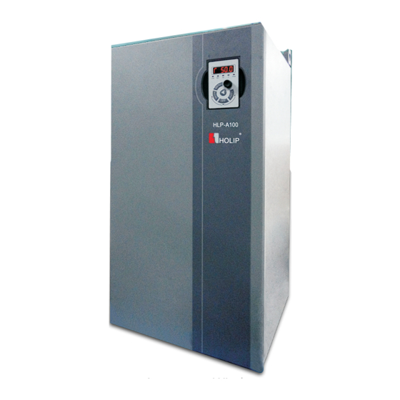
Holip HLP-A100 Series Manuals
Manuals and User Guides for Holip HLP-A100 Series. We have
1
Holip HLP-A100 Series manual available for free PDF download: Operating Manual
Holip HLP-A100 Series Operating Manual (188 pages)
Vector inverter
Brand:
Holip
| Category:
Inverter
| Size: 7 MB
Table of Contents
Table of Contents
4
Index
4
Chapter 1 Safty Precautions
8
Before Power-Up
8
Introduction
8
Safety Precautions
8
During the Operation
10
During the Power-Up
10
After the Power-Off
11
Chapter 2 Standards and Specifications
12
Particular Specifications
13
Technical Specifications
14
Checks before Installation
18
Installation Dimensions
18
Dimensions of LCP
18
Label Description
12
Significance of the Type Code
12
Chapter 3 Installation and Wiring
18
Dimensions of the Inverter
19
Installation Dimensions of the Inverter
20
Electrical Installation in General
20
Details of Terminal Tightening Torques
20
Installation and Wiring
20
Installation and Direction
21
Side by Side Installation
21
Single Installation
21
Main Circuit Terminals
22
Terminals of the Main Circuit
22
Upper and Lower Installation
22
Wiring Terminal
22
11-22Kw & 90-220Kw Control and Relay Terminals:
23
30-75Kw Control and Relay Terminals:
23
Description of Main Circuit Terminals
23
I/O Control Terminals
23
Description of I/O Control Terminals
24
Basic Connection Diagram of HLP-A100 Series Inverter
26
Wiring
26
Precautions for the Main Circuit Wiring
27
LCP Digital Operator
28
Preset Reference by LCP
28
Quick to Set Parameters
28
Chapter 4 Operation and Display Interface
28
FWD/REV Status
29
Data Read-Outs
30
View Alarm Record
32
View State Parameter
33
LED Display
34
Chapter 5 Parameter Overview
35
Basic Settings
61
Chapter 6 Parameter Description
61
Parameter Group 00: Operation/Display
61
Set-Up Operations
62
Custom Readout Min
63
Link Set-Ups
63
Terminal State
63
Custom Readout Max
64
LCP Display Option
64
Parameter Group 01: Load and Motor
66
Motor Date
67
Motor Current
68
Motor Frequency
68
Motor Norminal Speed
68
Adv.motor Data
69
Main Reactance(Hh) Dep.motor Data
69
Motor Cable Length
69
Motor Poles
69
V/F Characteristic-V
70
Flying Start
74
Function at Stop
74
Parameter Group 02: Brakes
76
Activate Brake Speed
78
Mechanical Brake
78
Over-Voltage Control
78
Minmum Reference
79
Parameter Group 03: Reference/Ramps
79
Reference Range
79
Jog Speed
81
Parameter Group 04: Limits/Warnings
88
Bypass Speed from
92
Bypass Speed to
92
Digital Output DO Mode
93
Parameter Group 05: Digital Input/Output
93
Pulse Input
99
Terminal DI4 High Frequency
99
Terminal DI4 Low Ref./Feedback
99
DO1 Pulse Output
100
Parameter Group 06: Analog In/Out
102
Parameter Group 07: Controller
110
Parameter Group 08: Comm. and Options
113
Parameter Group 13: Simple PLC
117
Start Event
118
Reset Simple PLC
119
Stop Event
119
Comparator Operand
120
Comparator Operator
120
Comparators
120
Comparator Value
121
Logic Rule Boolean 1
121
Logic Rule Operator 1
121
Simple PLC Timer
121
Logic Rule Boolean 2
122
Logic Rule Operator 2
122
Simple PLC Action
123
Simple PLC Event
123
Damping Gain Factor
125
Overmodulation
125
Parameter Group 14: Special Functions
125
Switching Frequency
125
Automatic Restart Time
126
Function at Mains Imbanlance
126
Low Voltage Mode
126
Reset Mode
126
Action at Inverter Fault
127
Current Limit Control
127
Operation Mode
127
Trip Lock
127
AEO Min. Magnetisation
128
Energy Optimising
128
VT Level
128
DC Voltage Compensation
129
Fan Control
129
Output Filter
129
RFI Filter Switch
129
Min. Switching Frequency
130
Operating Days
130
Parameter Group 15: Drive Information
130
Running Hours
130
Fault Log:error Code
131
Over Voltages
131
Reset Kwh Counter
131
FC Type
132
Power Section
132
Software Version
132
Voltage
132
FC Serial Number
133
Parameter List
133
Power Card Serial Number
133
Software ID Power Card
133
Control Word
134
Parameter Group 16: Data Readouts
134
Reference
134
Active Set-Up
135
Communication Status Word
135
Status Word
135
Custom Readout
136
Motor Speed [RPM]
136
Power(Hp)
136
Power(Kw)
136
DC Link Voltage
137
Inverter Temp.
137
Inverter Thermal
137
Motor Thermal
137
External Reference
138
Pulse Reference
138
Wobble Length
138
Analog Input AI
139
Analog Input VI
139
Terminal AI Setting
139
Terminal VI Setting
139
Encoder Input
140
Pulse Input DI4
140
Pulse Output DO1
140
Relay Output
140
Alarm Word
141
FC Port Reference
141
Parameter Group 25: App. Functions Cascade
143
Pump Type Selection
149
Water Level Control
149
Water Level Signal Source
149
High Warter Level
150
Low Water Level
150
Overrun Water Level
150
Scarcity Water Level
150
Alarm Handl Selection
151
Water Level Dead Band
151
Parameter Group 30: App. Functions Wobble
152
Wobble Start Mode
152
Centre Frequency Mode
153
Dwell Frequency
153
Dwell Time
153
Delta Frequency Mode
154
Delta Frequency Percentage
154
Jump Frequency Percentage
154
Wobble up Time
154
Max. Radom Ratio
155
Min. Radom Ratio
155
Wobble Length Source
155
Wobble Random
155
Wobble Restore Mode
156
Wobble Stage Store
156
Motor Parameter Adaption
157
Chapter 7 Quick Application Guide
157
Using Lcp to Control the Drive [Hand
157
Set-Up Selection
158
Select the Menu with Digital Input DI1
158
Using Digital in Terminals to Control the Drive [AUTO]
158
Potentiometer Reference
159
Connect Two-Wire Transductor to Terminal AI
159
Reference for Pulse Input
160
Multi-Speed
160
Speed Up/Down
161
Pulse Start/Stop
162
Digital Speed Up/Down
162
Configuration Mode
163
Simple PLC
165
Order Execution
165
Parallel Execution
167
Braking Resistor
168
Chapter 8 Accessory Specification
168
External LCP Communication Cable
169
LCP Mounting Kit
169
Mounting Steps
169
Chapter 9 EMC
170
Fault List
171
Emc–Correct Installation
170
Chapter 10 Warnings/Alarms and Fault Handling
171
Fault Indication and Trouble Shooting
175
Chapter 11 Maintenance
177
Note
177
Storage and Transport
177
Chapter 12 Communication Protocol
178
Coil Addressing
178
FC Control Word
178
Format Specification
178
Detect Inverter Output F Requency
180
Read Coil Status
180
Read Holding Registers
181
Receive Data
181
Transmit Data
181
Force Single Coil
182
Preset Single Register
182
Force Multiple Coils
183
Frequency Conversion Specification
184
Preset Multiple Regs
184
Read/Write Array
185
Exception Code
186
Receive Data 2
186
Transmit Data 2
186
Advertisement
Advertisement
Related Products
Holip HLP-A Series
Holip HLP- C+ Series
Holip HLPC+00D423B
Holip HLPC+0D7543B
Holip HLPC+01D543B
Holip HLPC+01D523B
Holip HLPC+02D223B
Holip HLP-P Series
Holip HLPSV03D721A
Holip HLPSV00D423A
Holip Categories
Inverter
Air Compressor
More Holip Manuals
Login
Sign In
OR
Sign in with Facebook
Sign in with Google
Upload manual
Upload from disk
Upload from URL