Sign In
Upload
Manuals
Brands
HK Audio Manuals
Stereo System
Cohedra Compact
HK Audio Cohedra Compact Manuals
Manuals and User Guides for HK Audio Cohedra Compact. We have
1
HK Audio Cohedra Compact manual available for free PDF download: Manual
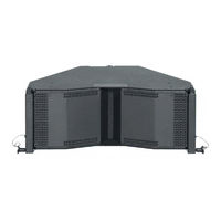
HK Audio Cohedra Compact Manual (105 pages)
Brand:
HK Audio
| Category:
Stereo System
| Size: 12.09 MB
Table of Contents
Table of Contents
5
1 Line Array Approaches in Recent Years
6
2 Development Objectives
7
High Frequency Range
7
Middle Frequency Range
7
Low Frequency Range
7
3 Emphasized Radiation Technology
7
The High Frequency Wave Front
8
Midrange
9
The Subwoofer-Truest Dynamic Response
9
CDR 208 MID/High Enclosure
9
Table of Contents
22
2 Warranty and Liability
23
Intended Use
23
Unintended Use
23
3 Important Notes on Safety
23
Responsibilities of the Operator
23
Storage, Maintenance, Inspection and
24
Technical Specifications of
24
Maximum Permissible Number of Flown COHEDRA
24
MID/High Units
24
MID/High Enclosures
24
Table 1: Weight of MID/High Enclosures
24
Maximum Number of Flown COHEDRA CDR 210 F Subwoofers
25
Ground-Stacked MID/High Enclosures
25
Pick Points for Flying MID/High Enclosures
25
Structural Modifications of Rigging Hardware
25
Original HK AUDIO
25
Initiation and Operation
25
Fig. 3: Top Rigging Frame
26
Fig. 4: Shackles for Attaching Motors, Straps
26
Fig. 5: Bottom Rigging Frame
26
Fig. 6: Lashing Strap for Curving the Array
26
Fig. 7: Quick-Release Pin
26
5 Determining the Curving Angle between Two COHEDRA
27
Fig. 9: Setting the Curving Angle on a Flown Array
27
Fig. 11: Open Case with Four MID/High Range Enclosures
28
Fig. 12 A-G: Turning the Connector Component
28
Fig. 13: Mounting the Top Rigging Frame
28
7 Mounting the Top Rigging Frame
29
9 Attaching the Bottom Rigging Frame and Raising the MID/High Array
31
The Top Rigging Frame
31
Fig. 18: Mounting the Bottom Rigging Frame
31
Fig. 19: Attaching the Lashing Strap / Second Motor between the Top and Bottom Rigging Frames
31
10 Ground Stacking
32
Ground Stacking with the Stack Frame
32
11 Setting up Subwoofers
32
Sub Array
32
Fig. 21: Groundstack with CDR 210 F Sub and CDR 208 S/T
32
Bass Cluster/ Stacking
33
Bass Clusters in Blocks
33
Fig. 22: CDR 210 Sub Array
33
Fig. 23: CDR 210 Sub Cluster
33
12 Flying CDR 210 F Subs
34
13 The SL 218 as a Bass Supplement
34
14 Operating the System
34
Fig. 24: CDR 210 Sub Cluster in Blocks
34
15 Disassembling and Removing the System
35
Fig. 25: Flown CDR 210 F Bass Array Next to MID/High Array
35
Fig. 26: the CDR 210 F Sub's Curving Angle
35
Fig. 27: Pin Assignment of Channels 1-4
35
Use/Fig. 16: Hoisting the Top Four
36
1 Use
36
Fig. 16: Hoisting the Top Four
36
Intended Use
37
Unintended Use
37
Warranty and Liability
37
Important Notes on Safety
37
Rigging Hardware
38
Responsibilities of the Operator
38
Of COHEDRA ® Compact Rigging Hardware
38
Technical Specifications of Fig
38
COHEDRA ® Compact Rigging Hardware
38
COHEDRA ® Compact MID/High Units
38
Maximum Permissible Number of Flown
38
Table 2: Weight of CDR 210 F Sub
39
Pick Points for Flying COHEDRA Compact Enclosures
39
Structural Modifications of COHEDRA ® Compact Rigging Hardware
39
Original HK Audio ® Accessories
39
Initiation and Operation
39
Components and Applications of COHEDRA ® Compact Rigging Hardware
40
Flying Enclosures Using Quick-Release Pins
40
Flying Arrays with Lightweight Rigging Frames
41
Determining the Splay between Two CDR 108 C Enclosures
41
Compression Mode
41
Fixed Mode
43
Flying CDR 210 C Subwoofers
44
Components
44
As an Independent Bass Array on a Second Rigging Frame
44
In Combination with CDR 108 C MID/High
44
Ground-Stacking
45
Without Subwoofer
45
With CDR 210 C Subwoofers
45
Operating the System
46
Connecting Speaker Cords
46
Activating PR 8 and PR 16 Amp Racks
46
Checking Individual MID/High Enclosures
46
Configuring the Controller Network Using Audio Controller Software
46
Tearing down and Transporting the System
47
Table of Contents
48
1 Introduction
49
Acoustic Simulation for Line Arrays
49
Remarks on SPL Calculation in CAPS
50
The Purpose of CAPS
51
2 Installing and Launching CAPS
51
System Requirements
51
Installation
51
Software Files
51
3 Launching CAPS
52
Menu File
52
Tools Menu
52
Options Menu
52
Help Menu
53
Location Panel
53
Setup Panel
53
Rigging Panel
54
Sub Array Panel
54
4 Creating a New Project
55
Entering Project Data
55
Entering Room Data
55
Entering Audience Areas
55
Defining the Simulation's Bandwidth
56
Aligning Enclosures Using the Optimization Function
57
Viewing the Sound Level Envelope
58
Viewing the Dispersion Pattern
59
Viewing Delay Times between MID/High Arrays and Stacked Subwoofers
59
6 Creating a Rigging Plan
60
7 Creating Horizontal Subwoofer Arrays
60
Fig. 1: 12 COHEDRA
61
Chapter 63 G
63
1 Digital Field Controller (DFC)
64
Connections
65
Display and Control Features
66
Basic Settings
66
Setting Delay Times
67
Adjusting the Equalizer
68
Storing Settings
68
Disabling Buttons on the DFC
68
Reset, Hot Reset and Master Reset Functions
68
Remote Control and Remote Monitoring
69
Overview of the Dfc's Menu Functions
69
Technical Data
70
2 Audio Controller Software Version 3.01
71
Installing Software
71
DFC Software Files
71
Connecting Hardware / the PC Interface
71
Launching DFC Software
72
Menu Bar
73
Adjusting Controller Parameters
75
Selecting the Audio Input
75
Selecting a Controller/Rack Mode
75
Activating the Key Lock on the DFC
76
Adjusting Master Channel Strip Settings
76
Adjusting the Bass, MID and High Channels
76
Graphic EQ
77
Forming Groups
78
Working with Several Programs
79
Loading New Filters into Dfcs
79
Chapter 81 H
81
2 COHEDRA ® Power Rack 8
82
COHEDRA ® Power Rack 16
82
Components
82
3 Design and Construction
83
Dimensons and Weights
83
4 Displays and Control Features
83
5 FU4 Fan Unit (with COHEDRA ® Power Rack 16 Only)
83
6 PS 32 Power Supply
84
Connections
84
L1, L2, L3 Circuit Breakers and
84
Neutral Conductor Check
84
Chapter 85 I
85
1 Protective Circuits
86
2 Limiter
86
3 Fan
86
4 Displays and Control Features
87
Mains Switch
87
LED Indicators
87
Channel A, Channel B Gain Knobs
87
Circuit Breaker
87
Mode Selector Switch
87
Limiter Switch
88
Ground Switch
88
5 Connectors
88
Mains
88
Signal Input A, Input B
88
Speaker Output A, Output B
89
Speaker Output A+B / Bridge
89
6 Installation in a Rack
89
7 Technical Data
89
Table of Contents
90
1 Front Panel Connections and Control Features
91
Analog Audio Input
91
DIGITAL AES/EBU Digital Audio Input
91
Patchbay PB5
91
PB 5 Patchbay
91
Ground Switch
92
MID/High - Sub Switches
92
Polarity Switch
92
2 Rear Panel Connectors
93
Patch Cables for Connecting the VX 2400 and DFC
93
Power Amp Channel Routing
93
MID/High-Sub
93
MID/High Only
94
Sub Only
94
Advertisement
Advertisement
Related Products
HK Audio Cohedra
HK Audio Cadis CAD 208
HK Audio Cadis CAD 115
HK Audio CONTOUR ARRAY
HK Audio COSMO Series
HK Audio COSMO LSM
HK Audio COSMO CRF-PB
HK Audio COSMO C-WB
HK Audio COSMO C-GSA
HK Audio COSMO CS-WB F
HK Audio Categories
Speakers
Speaker System
Stereo System
Subwoofer
Amplifier
More HK Audio Manuals
Login
Sign In
OR
Sign in with Facebook
Sign in with Google
Upload manual
Upload from disk
Upload from URL