Sign In
Upload
Manuals
Brands
Hioki Manuals
Test Equipment
3561
Hioki 3561 Internal Resistance Tester Manuals
Manuals and User Guides for Hioki 3561 Internal Resistance Tester. We have
1
Hioki 3561 Internal Resistance Tester manual available for free PDF download: Manual
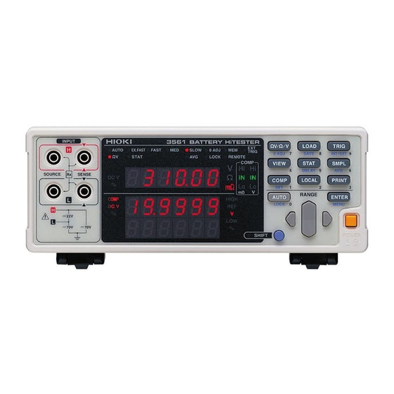
Hioki 3561 Manual (191 pages)
BATTERY HiTESTER
Brand:
Hioki
| Category:
Test Equipment
| Size: 18 MB
Table of Contents
Contents
3
Introduction
7
Verifying Package Contents
7
Options
7
Safety Information
8
Other Symbols
8
Overvoltage Categories
9
Accuracy
9
Operating Precautions
10
Instrument Installation and Operating Environment
10
Preliminary Checks
11
Measurement Precautions
11
Before Connecting and Powering on
12
Handling the Instrument
12
Handling the Test Leads and Cables
12
Product Overview
13
Features
14
Names and Functions of Parts
15
Front Panel
15
Main Display
16
Sub Display
16
Operating Keys
17
Rear Panel
18
Side View
18
Menu Display Sequence
19
Measurement Flowchart
20
Measurement Preparations
21
Preparation Flowchart
21
Connecting the Power Cord
22
Connecting the Optional Test Leads
23
About Test Leads
24
Turning the Power on and off
25
Selecting the Line Frequency
26
Measurement
27
Pre-Operation Inspection
27
Basic Measurement Example
28
Preparations
28
Instrument Settings
29
Zero-Adjustment
30
Selecting Measurement Mode
31
Setting Measurement Range
32
Manual Range Setting
32
Auto-Ranging
33
Switching from Auto-Ranging Back to Manual Range Selection
33
Setting Sampling Rate
34
Zero-Adjust Function
34
Wiring Method for Zero-Adjustment
34
Executing Zero-Adjustment
35
Clearing Zero-Adjustment
36
If Err02 Is Displayed
36
Displaying Measurement Results
37
Measurement Fault Detection
38
Overflow Display
38
Applied Measurement
39
Comparator Function
40
Comparator Setting Example
41
Comparator Judgment Beeper Setting
49
Comparator Execution Mode Setting
50
Comparator Threshold Method Selection
51
Upper and Lower Threshold Setting
52
Enabling and Disabling the Comparator Function
54
Comparator Judgment Results
55
Judgment Operation
55
Judgment Output
55
Switching between Measurement Value and Comparator Setting Displays
56
Trigger Function
57
Trigger Source Settings
57
Measurement with External Triggering
57
Trigger Delay Settings
58
Disabling the Trigger Delay Function
58
Averaging Function
59
Disabling the Averaging Function
59
Statistical Calculation Functions
60
Enabling/Disabling the Statistical Calculation Functions
61
Clearing Statistical Calculation Results
61
Automatic Clearing of Statistical Calculation Results after Printing
62
Importing Data
62
Confirming Statistical Calculation Results
62
Sending Statistical Calculation Results to the Printer
63
Memory Function
64
Key-Lock Function
66
Disabling Key-Lock
66
Panel Save Function
67
Saved Items
67
Panel Load Function
68
Self-Calibration
69
Measurement Value Output Function
70
Key Beeper Setting
71
Reset Function
72
Initial Factory Default Settings
73
External Control
75
Overview
75
External Control Input Functions
75
External Output Terminal Functions
75
Signal Descriptions
76
Pinout
76
Input Signals
77
Output Signals
78
ERR Output
79
Measurement Fault Output Signal Setting
80
Setting the EOC Signal
80
External Trigger Timing Chart
81
Internal Trigger Timing Chart
81
Internal Circuitry
83
External Control and External Output Terminal Ratings
83
External Control Terminals
83
External Output Terminals
84
Circuit Diagram
84
Application Examples
84
Printer
85
Connecting the Printer
86
Connecting the 9670 Printer to the Instrument
87
Connector Pinouts
87
Loading Recording Paper
88
Handling and Storing Recording Paper
88
Charging the Battery Pack
89
Installing the Battery Pack in the Printer
89
Selecting the Interface
90
Setting of the 9670 Printer
90
Printing Measured Values and Decision Results
91
Interval Printing
91
Printing Statistical Calculation Results
91
Example Printouts
92
RS-232C/GP-IB Interfaces
93
Overview and Features
93
Before Use
93
RS-232C Specifications
94
GP-IB Specifications
94
Selecting the Connections and Protocol
95
Attaching the Connector
95
Connecting to a PC/AT-Compatible Machine
96
Connecting to an NEC PC9801 or PC9821 Series Desktop PC
96
Selecting the Interface
97
Communication Methods
98
Message Format
98
Program Messages
98
Response Messages
99
Command Syntax
99
Command Program Headers
99
Quer Program Header
99
Message Terminators
100
Message Unit Separator
100
Header Separator
100
Data Separator
100
Data Formats
101
Character Data
101
Decimal Numeric Data
101
Compound Command Header Omission
102
Output Queue and Input Buffer
103
Status Byte Register
104
Service Request Enable Register
105
Standard Event Status Register (SESR)
106
Standard Event Status Enable Register
107
Device-Specific Event Status Registers
107
Register Reading and Writing
108
GP-IB Commands
108
Initialization Items
109
Local Function
109
To Cancel the Remote State
109
Message List
110
Standard Commands
110
Device-Specific Commands
111
Message Reference
116
System Data Command
117
Internal Operation Command
117
Queries Device ID
117
Initialize Device
117
Synchronization Commands
118
Status and Event Control Commands
118
Set the OPC Bit of SESR When Finished All Pending Operations
118
Respond "1" When Finished All Pending Operations
118
Set and Query the Standard Event Status Enable Register
119
Query and Clear the Standard Event Status Register
119
Set and Query the Service Request Enable Register
120
Query the Status Byte and MSS Bit
120
Request a Sample
120
Set and Query Device-Specific Event Status Enable Register ESER0/1
121
Read Device-Specific Event Status Registers ESR0/1
121
Select and Query the Measurement Mode Setting
122
Set and Query the Resistance Measurement Range
122
Set and Query the Voltage Measurement Range
122
Set and Query the Auto-Ranging Setting
123
Cancel Zero-Adjustment
123
Execute Zero Adjustment and Query the Result
123
Select and Query the Sampling Rate Setting
123
Set and Query the Averaging Function Setting
124
Set and Query the No. of Samples to Average
124
Set and Query the Comparator
124
Set and Query Comparator Judgments
125
Set and Query the Comparator Execution Mode Setting
125
Set and Query the Comparator Upper Threshold Setting
126
Resistance Measurement
126
Voltage Measurement
126
Set and Query the Comparator Lower Threshold Setting
127
Set and Query the Comparator Reference Value
128
Set and Query the Comparator Decision Tolerance Setting
129
Query Comparator Judgment Results
130
Execute Statistical Functions
130
Clear Statistical Calculation Results
130
Query the Data Count
131
Query the Mean Value
131
Query the Maximum Value
132
Query the Minimum Value
132
Query Standard Deviation
133
Query the Process Capability Indices
134
Set and Query the Memory Function State
134
Clear Instrument Memory
134
Query the Memory Data Count
135
Query Memory Data
135
Execute Self-Calibration
136
Self-Calibration State and Setting
136
Set and Query Measurement Value Output Upon Triggering
136
Set and Query the Key Beeper Setting
137
Select and Query the Line Frequency Setting
137
Set and Query the Key-Lock State
137
Set and Query EXT I/O Lock
138
Set Local Control
138
Save and Load Measurement Values
138
Backup Current Measurement Configuration
138
Set and Query the Header Present Setting
139
Set and Query Error Output Timing
139
Set and Query the Terminator
139
System Reset
140
EXT I/O Output
140
EXT I/O Input
140
Triggering System Description
141
Measurement Flow
142
Continuous Measurement Setting
143
Trigger Wait Setting
143
Set and Query the Trigger Source
144
Enable/Disable and Query Trigger Delay
144
Set and Query Trigger Delay Interval
145
Read the Latest Measurement
145
Execute a Measurement and Read the Measured Values
146
Measurement Value Formats
147
Command Compatibility with the Model 3560 AC
148
Model 3560 Measurement Value Formats
151
Basic Data Importing Methods
152
Free-Run Data Importing
152
Importing by Host Triggering
152
Importing Data by TRIG Key or TRIG Terminal
152
Sample Programs
153
RS-232C Communications
153
Simple Resistance Measurements
153
Measure Resistance by PC Key
154
External Trigger Measurement
155
Set Measurement State
157
GP-IB Communications
158
Simple Resistance Measurement
158
Basic Specifications
163
Response Time
164
Display Device
166
External Interfaces
166
Guaranteed Accuracy Conditions
167
General Specifications
168
Maintenance and Service
169
Troubleshooting
169
Cleaning
170
Error Display
170
Appendix
171
Precautions for Making Custom Test Leads
171
AC Four-Terminal Method
173
Synchronous Detection System
174
Configuration and Extension of the Test Leads
175
Reducing Induced Voltage
175
Effect of Eddy Currents
176
Calibration of the Ohmmeter
177
Calibration of the Voltmeter
177
Test Lead Options
178
Rack Mounting
179
Dimensional Diagram
181
Index
183
Advertisement
Advertisement
Related Products
Hioki 3561-01
Hioki 3560
Hioki 3555
Hioki 3511-50
HIOKI 3551
Hioki 3554
Hioki 3504-50 C HiTester
Hioki 3504-60 C HiTester
Hioki HiTESTER 3540
Hioki 3504-10
Hioki Categories
Measuring Instruments
Test Equipment
Data Loggers
Multimeter
Accessories
More Hioki Manuals
Login
Sign In
OR
Sign in with Facebook
Sign in with Google
Upload manual
Upload from disk
Upload from URL