Sign In
Upload
Manuals
Brands
Hinds Instruments Manuals
Modulator
PEM-100
Hinds Instruments PEM-100 Manuals
Manuals and User Guides for Hinds Instruments PEM-100. We have
1
Hinds Instruments PEM-100 manual available for free PDF download: User Manual
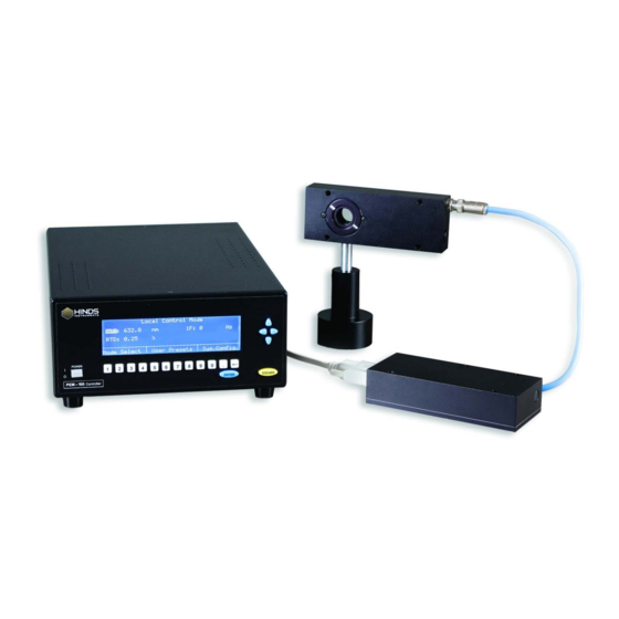
Hinds Instruments PEM-100 User Manual (100 pages)
PHOTOELASTIC MODULATOR
Brand:
Hinds Instruments
| Category:
Modulator
| Size: 1 MB
Table of Contents
Table of Contents
5
Table of Figures
9
Operators' Safety Summary
13
Terms
13
PEM-100 Controller Labels
13
Figure S.1 Compliance Labeling
13
AC Power Source
14
Do Not Operate Without Cover
14
Unpacking the PEM 100
15
Shipping Damage Check
15
Unpacking the PEM Optical Head
16
Special Instructions for I/FS50 Optical Head
16
Figure S.1 I/FS50 Remove Shipping Disk
16
Figure S.2 I/FS50 Remove Blue Foam Disk
17
Figure S.3 I/FS50 Remove Inner Blue Foam & Lens Tissue
17
Special Instructions for II/FS42 & II/IS42 Optical Head
18
Figure S.4 II/FS42 Remove Shipping Disk & Lid
18
Figure S.5 II/FS42 Remove Unpacking Instructions
19
Figure S.6 II/FS42 Remove Blue Foam & Yellow Clips
19
Figure S.7 Junction between Optical Element and Transducer
20
Figure S.8 Removing Yellow Transducer Support Clips
20
1 Introduction
23
Overview
23
Figure 1.1 PEM 100 Photoelastic Modulator
23
PEM-100 Controller Accessories
24
Rack Mounting Kit
24
RS232 Converters
24
2 PEM-100 Controller
25
PEM-100 Controller Front Panel
25
Figure 2.1 PEM-100 Front Panel off State
25
PEM-100 Controller Front Panel Buttons
26
PEM-100 Controller Rear Panel
27
PEM-100 Controller Rear Panel Connections
27
Figure 2.2 PEM-100 Rear Panel
27
Figure 2.3 RS232 Connections
28
3 Modulator Head Assembly
29
Optical Head
29
Figure 3.1 Model I/FS50 Optical Head Dimensions
29
Figure 3.2 Model II/FS42 Optical Head Dimensions
30
Figure 3.3 Model II/ZS50 Optical Head Dimensions
30
Figure 3.4 II/FS84 Optical Head Dimensions
31
Figure 3.5 II/ZS37 Optical Head Dimensions
31
Electronic Head
32
Figure 3.6 Electronic Head Dimensions
32
4 Initial Set-Up
33
Connecting the PEM Optical and Electronic Heads
33
Figure 4.1 Connecting I/FS50 Optical Head to Electronic Head
34
Figure 4.2 Connecting II/ZS50 Optical Head to Electronic Head
34
Figure 4.3 Connecting II/ZS50 Optical Head to Electronic Head (Cross Connection)
35
Figure 4.4 Connecting 1/FS50 Optical Head with ATC Option to Electronic Head
36
Optical Bench Set-Up
37
Functional Check
37
Figure 4.5 Block Diagram for Oscilloscope Calibration Method
37
Figure 4.6 Oscilloscope Waveform for PEM Set to 0.25 Wave Retardation between Crossed Polarizers and PEM 1F Reference Signal
38
5 PEM-100 Controller Display
39
Display Modes
39
Local Control Mode
39
Figure 5.1 Local Control Mode Display
39
Voltage Control Mode
40
Figure 5.2 Voltage Control Mode Display
40
Remote Control Mode
41
Figure 5.3 Remote Control Mode Display
41
User Presets
42
Local Control Presets
42
Figure 5.4 Local Control Mode - User Presets Menu
42
Voltage Control Presets
43
Figure 5.5 Voltage Control Mode - User Presets
43
System Configuration
44
Screen Settings
44
Restore Defaults
44
Figure 5.6 System Configuration Menu
44
RS232 Settings
45
System Info
45
Table 5.1 PEM-100 Controller RS232 Settings
45
Table 5.2 PEM-100 Controller Calibration & SW Suffix
45
6 Operating the PEM-100 Controller
47
Front Panel Operation
47
Power up
47
Figure 6.1 PEM-100 Controller Front Panel
47
Factory Default Parameters
48
Setting Front Panel Parameters
48
Setting Wavelength
48
Setting Retardation
49
Setting the Frequency
49
Setting Vcontrol
49
Selecting Factory Default Presets
50
Saving User Defined Presets
50
Resetting the Controller to Default Parameters
50
Local Control Mode Factory Defaults
51
Voltage Control Mode Factory Defaults
51
Table 6.1 Local Control Mode Factory Defaults
51
Table 6.2 Voltage Control Mode Factory Defaults
51
7 PEM Control Software
53
Installing the PEM Control Software
53
Setup of PEM-100 Controller for Use with PEM Control Software
53
Launching the PEM Control Software and Verifying Communication with the PEM-100 Controller
54
Choosing the Proper Headset Type
54
Operating the PEM Control Software
55
Figure 7.1 Head Type Selections
55
Figure 7.2 Main Display Screen
56
Main Display Screen
56
Figure 7.3 Advanced Setting Dialog Box
58
Control Operation
59
Figure 7.4 V Control Mode Dialog Box
59
8 Command Line Interpreter (CLI)
61
Example Setup of PEM-100 Controller for Use with the CLI
61
Table 8.1 CLI Port Settings & ASCII Setup
61
PEM-100 'Command Line Interpreter (CLI)' Command Descriptions
63
Table 8.2A PEM-100 Command Line Interpreter Command Descriptions
63
Table 8.2B PEM-100 Command Line Interpreter Command Descriptions
64
9 Troubleshooting
65
Troubleshooting Guide - Symptoms & Possible Remedies
65
Table 9.1A Troubleshooting Guide - Symptoms & Possible Remedies
65
Figure 9.1 Display - no Connection between Head-Set & Controller
66
Table 9.1B Troubleshooting Guide - Symptoms & Possible Remedies
66
Over Limit Conditions in Local Control & Voltage Control Modes
67
Figure 9.2 Display - Retardation over Limit Message
67
Figure 9.3 Display - Voltage over Limit Message
67
10 Maintenance
69
Calibration
69
Adjustment of Peak Retardation Calibration
69
Power Line Fuse Replacement
70
Figure 10.1 Opening the Power Fuse Holder
70
Cleaning
71
Recommended Optics Cleaning Solutions
71
Figure 10.2 Fuses Properly Inserted in Fuse Holder
71
Cleaning the Optics
72
Figure 10.3 Direction of Cotton Swab Wiping Motion
72
Cleaning the Controller
73
Figure 10.4 Junction between Optical Element and Transducer
73
A Calibration
75
PEM 100 Calibration
75
Calibration Theory
76
Figure A.1 Typical Optical Setup
76
Light Sources for Modulator Calibration
77
Calibration Using an Oscilloscope
78
Figure A.2 Oscilloscope Calibration Method
78
Figure A.3 Waveform for Half-Wave Retardation
79
Figure A.4 Retardation 90% of Half-Wave
79
Figure A.5 Retardation 110% of Half-Wave
80
Figure A.6 Waveform for a Retardation of Four Half-Waves
80
Multiple Reflection Techniques
81
Static Waveplate Techniques
81
Figure A.7 Setup for Double Pass Modulation
81
Bessel Function Zero Methods
82
Figure A.8 Determining the Controller Settings for Which J = 0
82
Bessel Function Ratio Methods
83
Parallel Polarizer Calibration at a Single Wavelength
84
Figure A.9 Ratio V
85
Figure A.10 Ratio V
86
B Specifications
89
General- Controller
89
Displayed Parameter Specifications
89
Input / Output Specifications
90
Environmental
90
Approvals
90
EMC & Safety Standards
90
C Optical Head Specifications
91
Advanced Thermal Control (ATC) Option Specifications
91
D User Support Information
93
PEM 100 Limited Warranty
93
Exclusions
93
Overview of the PEM 100 Help System
94
Table D.1 Contacting Technical Support
94
Return for Repair Procedure
95
Packaging
95
Items to Include
95
Shipping Arrangements
95
Return Shipping Address
96
Shipping Costs
96
Index
97
Advertisement
Advertisement
Related Products
Hinds Instruments PEM200
Hinds Instruments PEM-CSC
Hinds Instruments Categories
Modulator
Laboratory Equipment
Measuring Instruments
Security Sensors
Microscope
More Hinds Instruments Manuals
Login
Sign In
OR
Sign in with Facebook
Sign in with Google
Upload manual
Upload from disk
Upload from URL