
Related Manuals for Hinds Instruments PEM-100

Summary of Contents for Hinds Instruments PEM-100
- Page 1 PEM-100 PHOTOELASTIC MODULATOR USER MANUAL Hinds Instruments, Inc. P/N: 010-0000-021 UM Rev H...
- Page 2 Hinds Instruments, Inc. In all respects, the English version of this manual is controlling. The PEM-100 is covered by the following US patents: (1) 7,800,845, (2) 7,495,205, (3) 6,970,278, (4) 6,906,844, (5) 6,867,863, (6) 5,886,810, (7) 5,744,721, (8) 5,652,673.
- Page 3 CAUTION! DO NOT turn on your modulator unless the optical head and the electronic head are connected by the head-to-head interconnect cable. SERIOUS DAMAGE MAY RESULT!
-
Page 5: Table Of Contents
RS232 Converters ......................12 2 PEM-100 Controller ....................13 PEM-100 Controller Front Panel ................. 13 PEM-100 Controller Front Panel Buttons ................14 PEM-100 Controller Rear Panel ................15 PEM-100 Controller Rear Panel Connections ..............15 3 Modulator Head Assembly ..................17 Optical Head ...................... - Page 6 7 PEM Control Software ..................... 41 Installing the PEM Control Software ..............41 Setup of PEM-100 Controller for use with PEM Control Software ....41 Launching the PEM Control Software and verifying communication with the PEM- 100 Controller ...................... 42 Choosing the Proper Headset Type ..............
- Page 7 Table Of Contents EMC & Safety Standards ..................78 C Optical Head Specifications ..................79 Advanced Thermal Control (ATC) Option Specifications: ........ 79 D User Support Information ..................81 PEM 100 Limited Warranty ................. 81 Exclusions .......................... 81 Overview of the PEM 100 Help System .............. 82 Return For Repair Procedure ................
- Page 8 Table Of Contents viii PEM 100 User Manual...
-
Page 9: Table Of Figures
Figure S.7 Junction between Optical Element and Transducer ........8 Figure S.8 Removing Yellow Transducer Support Clips ..........8 Figure 1.1 PEM 100 Photoelastic Modulator ..............11 Figure 2.1 PEM-100 Front Panel OFF State ..............13 Figure 2.2 PEM-100 Rear Panel ..................15 Figure 2.3 RS232 Connections ..................16 Figure 3.1 Model I/FS50 Optical Head Dimensions ............17... - Page 10 Table of Figures Figure 6.1 PEM-100 Controller Front Panel ..............35 Figure 7.1 Head type selections ..................43 Figure 7.2 Main Display Screen ..................44 Figure 7.3 Advanced Setting Dialog Box ................ 46 Figure 7.4 V Control Mode Dialog Box ................47 Figure 9.1 Display –...
- Page 11 Table of Tables Table 5.1 PEM-100 Controller RS232 Settings ..............33 Table 5.2 PEM-100 Controller Calibration & SW Suffix ..........33 Table 6.1 Local Control Mode Factory Defaults .............39 Table 6.2 Voltage Control Mode Factory Defaults ............39 Table 8.1 CLI Port Settings & ASCII Setup ..............49 Table 8.2a PEM-100 Command Line Interpreter Command Descriptions ....51...
- Page 12 Table of Tables PEM-100 User Manual...
-
Page 13: Operators' Safety Summary
PEM-100 Controller Labels The serial number and CE certification labels are located at the lower right corner on the PEM-100 Controller rear panel as shown in figure S.1 below. Figure S.1 Compliance Labeling PEM 100 User Manual... -
Page 14: Ac Power Source
Do Not Operate Without Cover To avoid personal injury, do not operate the PEM-100 Controller without the cover. Ensure the controller ventilation openings located on the top and bottom of the enclosure are clear of any obstructions. -
Page 15: Unpacking The Pem 100
A return authorization number (RMA) will be assigned to you. See Overview of the PEM 100 Help System on page 82 for further contact information. 7. Return approved items to Hinds Instruments Inc. at the following address: Hinds Instruments, Inc. 7245 NW Evergreen Pkwy Hillsboro, OR 97124-5850 8. -
Page 16: Unpacking The Pem Optical Head
Unpacking the PEM-100 Unpacking the PEM Optical Head CAUTION PLEASE USE CARE when unpacking the PEM optical head, for this assembly is very fragile. Please follow the unpacking instructions carefully. Unless this is done, the PEM system will not operate and the optical head may be irreversibly damaged. -
Page 17: Figure S.2 I/Fs50 Remove Blue Foam Disk
Unpacking the PEM Optical Head 3. Remove the blue foam disk. Blue foam disk Figure S.2 I/FS50 Remove Blue Foam Disk 4. Carefully remove the inner blue foam and lens tissue from this side of the optics, thus exposing the PEM optics. Inner Foam &... -
Page 18: Special Instructions For Ii/Fs42 & Ii/Is42 Optical Head
Unpacking the PEM-100 6. Blow air on the optics to ensure there is no lint or dust particles on the optic surfaces. CAUTION Use only oil free air when blowing lint or dust particles from the optic surfaces. If using canned air, hold the container upright or liquid will spray onto the optic surface. -
Page 19: Figure S.5 Ii/Fs42 Remove Unpacking Instructions
Unpacking the PEM Optical Head Figure S.5 II/FS42 Remove Unpacking Instructions 4. Remove the blue foam and lens tissue. NOTE: The foam on the other side of the optics will be removed through the shipping disk on the opposite side of the PEM. Blue Foam Qty 2 Yellow Rubber Clips Figure S.6 II/FS42 Remove Blue Foam &... -
Page 20: Figure S.7 Junction Between Optical Element And Transducer
Unpacking the PEM-100 CAUTION Be very careful to protect the optic and transducer bond. Do not apply excessive force to this bonded junction when removing the yellow packing supports. Optical Element Junction Transducer Figure S.7 Junction between Optical Element and Transducer 6. - Page 21 Unpacking the PEM Optical Head 8. Turn the PEM optic head over and remove the shipping disk. 9. Carefully remove the inner blue foam and lens tissue. 10. Blow air on the optics to ensure there is no lint or dust particles on the optic surfaces.
- Page 22 Unpacking the PEM-100 PEM 100 User Manual...
-
Page 23: Introduction
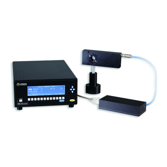
PEM including wide acceptance angle, large aperture and high modulation ”purity.” Figure 1.1 provides an overview of the PEM 100 photoelastic modulator system which includes the PEM-100 Controller, Optical Head, Electronic Head as well as the Head-to-Head Interconnect cable and the Head-to-Controller cable. OPTICAL HEAD... -
Page 24: Pem-100 Controller Accessories
Chapter 1: Introduction PEM-100 Controller Accessories Rack Mounting Kit The PEM-100 Controller can be mounted in a Hinds Instruments rack mount kit (PN: 023-0000-184). RS232 Converters Two RS232 converters are available: • RS232 to IEEE-488 Converter, Hinds PN: 020-2404-001 • RS232 to USB Converter, Hinds PN: 036-9003-120... -
Page 25: Pem-100 Controller
PEM-100 Controller PEM-100 Controller Front Panel The PEM-100 Controller front panel consists of a keypad user interface and a backlit LCD display. These features allow the user to control the peak retardation and wavelength settings of the modulator head set. -
Page 26: Pem-100 Controller Front Panel Buttons
Chapter 2: PEM-100 Controller PEM-100 Controller Front Panel Buttons • Power Button: Press the POWER key in to power the PEM-100 ON, depress the key to power the unit OFF. The symbols to the left of the power button indicate the following: power ON ‘I’... -
Page 27: Pem-100 Controller Rear Panel
PEM-100 Controller Rear Panel All electrical/electronic connections to the controller are made on the rear panel. Figure 2.2 PEM-100 Rear Panel PEM-100 Controller Rear Panel Connections • RS232 Connection: The RS232 Serial Port connector is a male DB9, and the connections are given in figure 2.3 on the following page. -
Page 28: Figure 2.3 Rs232 Connections
Chapter 2: PEM-100 Controller + 5 V L R 6 2 1 0 K R S 2 3 2 T X R S 2 3 2 R X Figure 2.3 RS232 Connections • f Output: BNC female connector provides TTL output of PEM, first harmonic frequency. -
Page 29: Modulator Head Assembly
Modulator Head Assembly The transducer-optical element assembly (called the “optical assembly”) is the heart of a PEM 100 photoelastic modulator. It consists of a rectangular or octagonal “window” of optical material bonded to a quartz piezoelectric transducer. Both optical element and transducer are tuned to the same frequency. When connected to a driver circuit, this assembly oscillates and produces the time-varying birefringence which is the basis of operation of the PEM. -
Page 30: Figure 3.2 Model Ii/Fs42 Optical Head Dimensions
Chapter 3: Modulator Head Assembly Figure 3.2 Model II/FS42 Optical Head Dimensions Figure 3.3 Model II/ZS50 Optical Head Dimensions PEM 100 User Manual... -
Page 31: Figure 3.4 Ii/Fs84 Optical Head Dimensions
Optical Head Figure 3.4 II/FS84 Optical Head Dimensions Figure 3.5 II/ZS37 Optical Head Dimensions PEM 100 User Manual... -
Page 32: Electronic Head
Chapter 3: Modulator Head Assembly The optical head is connected to the electronic driver circuit (housed in the “electronic head”) by a head-to-head Interconnect cable. This assembly of the optical head, the electronic head, and the head-to-head interconnect cable comprises the “modulator head,” which should be regarded as a single unit. CAUTION Operation of the electronic head without the head-to-head cable and optical head connected should never be attempted. -
Page 33: Initial Set-Up
Initial Set-Up Before initial set-up, the PEM optic head should be unpackaged as described in Unpacking the PEM Optical Head on page 4. Connecting the PEM Optical and Electronic Heads There are two different connection configurations between the optical head and electronic head based upon the type of optical head used. -
Page 34: Figure 4.1 Connecting I/Fs50 Optical Head To Electronic Head
Chapter 4: Initial Set-up If there is a single, triax BNC connector on the optical and electronic heads, connect the blue triax Head-to-Head Interconnect cable provided. Figure 4.1 Connecting I/FS50 Optical Head to Electronic Head If there are dual standard BNC (coax) connectors on the optical and electronic heads, connect the dual black coaxial Head-to-Head Interconnect cables provided. -
Page 35: Figure 4.3 Connecting Ii/Zs50 Optical Head To Electronic Head (Cross Connection)
2. Connect the electronic head to the PEM-100 Controller using the Controller-to- Head cable. 3. Connect the power cord to the PEM-100 Controller and plug it into an AC power source. 4. Connect the RS232 serial interface cable to the computer (if used for remote control). -
Page 36: Figure 4.4 Connecting 1/Fs50 Optical Head With Atc Option To Electronic Head
Chapter 4: Initial Set-up Figure 4.4 Connecting 1/FS50 Optical Head with ATC Option to Electronic Head PEM 100 User Manual... -
Page 37: Optical Bench Set-Up
Optical Bench Set-up Optical Bench Set-up The optical bench and electronic configuration depend on the particular application required for the modulator. More detailed set-up information can be found at our website http://www.hindsinstruments.com/applications for an applications pull down menu. The most common optical and electronic setup for checkout and calibration of the modulator is shown in figure 4.5. -
Page 38: Figure 4.6 Oscilloscope Waveform For Pem Set To 0.25 Wave Retardation Between Crossed Polarizers And Pem 1F Reference Signal
The detector circuitry deserves some special comment. Care must be taken to ensure adequate frequency response, typically several times the PEM operating frequency. Pre-amplified photo detectors are available from Hinds Instruments that fit this need. See page 82 for contacting Hinds Instruments Inc. PEM 100 User Manual... -
Page 39: Pem-100 Controller Display
There are three available display modes: Local Control Mode, Voltage Control Mode and Remote Control Mode. Within each mode type are specific user presets and system configurations. Screens displayed within this chapter are taken from a PEM-100 Controller that is connected to an I/FS50 head set. Local Control Mode The Local Control mode displays and allows for adjustments to wavelength and retardation for the PEM-100. -
Page 40: Voltage Control Mode
ENTER and then arrow to the numbered preset you wish to save the current settings to and press ENTER once again to facilitate the save function. The PEM-100 Controller will retain the saved Local Control Mode user presets when the unit is powered off. -
Page 41: Remote Control Mode
Remote Control Mode The Remote Control Mode sets the PEM-100 controller to remote PC control by way of the PEM Control Software, user specific software or by a terminal program. To access the Remote Control Mode, use the arrow keys to navigate to Mode Select and press ENTER. -
Page 42: User Presets
Chapter 5: PEM-100 Controller Display User Presets The User Presets menu allows for the selection of initial factory loaded presets or saved user presets that were entered from within the Local Control Mode and Voltage Control Mode. Local Control Presets... -
Page 43: Voltage Control Presets
User Presets Voltage Control Presets Figure 5.5 Voltage Control Mode – User Presets The User Presets menu accessed through the Voltage Control Mode, allows for the selection of preset factory settings and/or previously loaded presets that were saved from within the Voltage Control Mode display menu. This menu, also allows the user to save current voltage control settings. -
Page 44: System Configuration
Chapter 5: PEM-100 Controller Display System Configuration The System Configuration menu allows for screen brightness adjustments and the ability to restore the factory default settings. This menu also displays the RS232 settings and system information Access the System Configuration Menu from the Local Control Mode, Voltage Control or Remote Control Mode. -
Page 45: Rs232 Settings
Compare the software part number displayed with the chart below to see what head type the PEM-100 Controller was calibrated for. Series System Info. SW Suffix I/FS -000 II/FS, IS -001 II/ZS -002 II/CF -003 II/SI -010 I/CF -011 Table 5.2 PEM-100 Controller Calibration & SW Suffix PEM 100 User Manual... - Page 46 Chapter 5: PEM-100 Controller Display PEM 100 User Manual...
-
Page 47: Operating The Pem-100 Controller
Operating the PEM-100 Controller Front Panel Operation Figure 6.1 PEM-100 Controller Front Panel Power Up When the instrument is first turned ON by pushing the POWER button, the controller is powered up with the factory default parameters. When the controller is turned OFF, the displayed parameters as well as newly loaded user presets are stored to memory. -
Page 48: Factory Default Parameters
Chapter 6: Operating the PEM-100 Controller Factory Default Parameters The PEM-100 controller is programmed at the factory with default settings of Wavelength = 632.8 nm and Retardation = 0. 25 λ. These settings are overwritten as desired by the user but they can be restored through the Sys. Config. then Restore Defaults menu path. -
Page 49: Setting Retardation
Front Panel Operation To set the controller to a different wavelength unit: 1. Arrow to the wavelength unit and press the ENTER button. 2. Arrow to desired wavelength unit (nm, µm or 1/cm) and press the ENTER button. Setting Retardation The factory default retardation is 0.250 λ... -
Page 50: Selecting Factory Default Presets
Chapter 6: Operating the PEM-100 Controller Selecting Factory Default Presets The controller contains preset parameters located within the User Presets menu. Depending upon which control mode (Local or Voltage) is displayed, the default preset selections for the associated mode will be displayed. -
Page 51: Local Control Mode Factory Defaults
Front Panel Operation Local Control Mode Factory Defaults The Local Control Mode factory default settings for User Presets are below. The factory defaults for Current Settings of wavelength and retardation are variable based upon controller configuration for head type used. Wavelength (nm) Retardation (λ) Current Settings... - Page 52 Chapter 6: Operating the PEM-100 Controller PEM 100 User Manual...
-
Page 53: Pem Control Software
Ensure the PEM-100 Controller is set up as follows before attempting to use the PEM Control Software: 1. The PEM-100 ‘RS-232’ port is connected to a COM port on the target computer. Note the COM port number. Use the ‘PEM - RS232 Communication Cable’ for this purpose. -
Page 54: Launching The Pem Control Software And Verifying Communication With The Pem-100 Controller
Chapter 7: PEM Control Software 3. Power ON the PEM-100 Controller and go to the ‘Sys.Config.\System Info’ menu to locate the ‘SW PN’. Write down the last 3 numbers of the ‘025-1000-XXX’ number. These numbers identify what type of controller and head-set you have and will be required by the PEM Control Software. -
Page 55: Operating The Pem Control Software
2. Now select the headset type recorded earlier (a reminder – to find the headset type, put the PEM-100 Controller in ‘Local Mode’ and go to the ‘Sys.Config.\System Info’ menu and view the SW PN. The XXX numbers of the 025-1000-XXX shown is the headset type. -
Page 56: Main Display Screen
Chapter 7: PEM Control Software Main Display Screen When launching the PEM Control Software, the main display screen will appear with the default settings as shown. This screen allows for adjustments to wavelength and retardation settings as well as provides selections for frequency and PEM head type. Figure 7.2 Main Display Screen PEM 100 User Manual... - Page 57 Operating the PEM Control Software Wavelength: The wavelength field displays the wavelength setting. Entering a different wavelength can be accomplished three ways: 1. Double click the wavelength displayed to highlight the setting and then enter a new wavelength. 2. Click and hold the slider adjustment below the wavelength display and drag the slider to the desired wavelength setting.
-
Page 58: Figure 7.3 Advanced Setting Dialog Box
See figure 7.2. Click on the PEM Head Type down▼ arrow and select the correct software part number. See ‘Setup of PEM-100 Controller for use with PEM Control Software’ on page 41. Click on the X to close the dialog box. -
Page 59: Control Operation
Operating the PEM Control Software V Control Operation The PEM Control Software provides for direct voltage control of the PEM head-set using the ‘V Control’ mode. Click on the ‘Settings/V Control’ from the main display screen to access the ‘V Control’ mode dialog box of the PEM Control Software. Figure 7.4 V Control Mode Dialog Box V Control: The V Control field displays the voltage control setting. - Page 60 Chapter 7: PEM Control Software 2. Enter the number of steps the scan will make in the Number of Steps field. The software will calculate the step size by dividing the range, defined by the starting and ending values, by the number of steps selected. 3.
-
Page 61: Command Line Interpreter (Cli)
CLI. Example Setup of PEM-100 Controller for use with the CLI 1. Connect the PEM-100 ‘RS-232’ port to the desired COM port on a computer. Use the ‘PEM - RS232 Communication Cable’ for this purpose. Note the COM port number. The computer must have a terminal program installed (example- Windows HyperTerminal). - Page 62 PEM-100. 6. Type the desired command from table 8.2 PEM-100 Control Line Interpreter Command Descriptions. Example: to set the PEM-100 retardation to ¼ wave, type: R:0250 then press Enter. To read the retardation setting, type: R then press Enter.
-
Page 63: Pem-100 'Command Line Interpreter (Cli)' Command Descriptions
Example Setup of PEM-100 Controller for use with the CLI PEM-100 ‘Command Line Interpreter (CLI)’ Command Descriptions PEM-100 Action/terminal Expected Terminal Command Description Remote Mode Remark characters typed Display Display Enter key pressed Enter *(ready indicator) No change Incorrect syntax or non- Is always followed by a ‘*’... -
Page 64: Table 8.2B Pem-100 Command Line Interpreter Command Descriptions
0.25 V:n.nnn and Vn.nnn. Correctly entered command followed by a ‘*’ Sets Vcntrl to n.nnn None No change n.nnn = 0.000 to 4.850 character on the next line. Table 8.2b PEM-100 Command Line Interpreter Command Descriptions PEM 100 User Manual... -
Page 65: Troubleshooting
(See Figure 8.1 on following page) - Ensure head-set is connected to the PEM-100 Controller via a 9-pin Head-to-Controller cable and that the optical head is connected to the electronic head. -
Page 66: Figure 9.1 Display - No Connection Between Head-Set & Controller
‘PEM Control’ software COM port needs to be changed after clicking display.” ‘Update Frequency’. - Ensure head-set is connected to the PEM-100 (See Figure 8.1 below) Controller and the controller RS232 port connected to the PC. The controller must be ON and set to REMOTE mode. -
Page 67: Over Limit Conditions In Local Control & Voltage Control Modes
Over Limit Conditions in Local Control & Voltage Control Modes Over Limit Conditions in Local Control & Voltage Control Modes For Local Control Mode, the controller senses over limit conditions when retardation or wavelength settings are too high. If this occurs, the following message will be displayed: Figure 9.2 Display - Retardation Over Limit Message For Voltage Control Mode, if the voltage input exceeds 4.85 volts, an over limit... - Page 68 Chapter 9: Troubleshooting PEM 100 User Manual...
-
Page 69: Maintenance
Maintenance Calibration PEM-100 modulators are calibrated at the factory before shipment. For most applications, recalibration is neither necessary nor appropriate. For a few applications, however, an on-site calibration procedure will be necessary if optimum performance is to be achieved. Hinds’ engineers will be glad to advise users on whether on site calibration is appropriate in a particular case. -
Page 70: Power Line Fuse Replacement
Chapter 10: Maintenance Power Line Fuse Replacement Two power line fuses (1 Amp, Slo-Blo, 5 x 20 mm) are present in the PEM-100 Controller. CAUTION In order to maintain proper fire and safety precautions, replace the power line fuses only with the type and value indicated. -
Page 71: Cleaning
Cleaning Figure 10.2 Fuses Properly Inserted In Fuse Holder Cleaning When the PEM was shipped, the surface was clean and defect free; however, the rigors of packing and shipping may leave some residue on the optical surface(s). A final cleaning of the optical surfaces may be required before using them in your system. -
Page 72: Cleaning The Optics
Chapter 10: Maintenance Cleaning the Optics Two cleaning methods recommended are the cotton swab method and the lens tissue method. These “wet drag” techniques of cleaning are effective methods for removing dust and light residue from most hard-coated optical surfaces. Warning To guard against electrical shock or instrument damage, never allow water to get inside the case. -
Page 73: Cleaning The Controller
When replacing the cover to the optics, tighten screws (Qty 4) until snug. Cleaning the Controller The exterior of the PEM-100 controller may be cleaned with a cloth dampened in water or a mild detergent solution. Do not clean with aromatic hydrocarbons, chlorinated solvents or methanol-based fluids since these chemicals can damage the front panel overlay and may possibly damage the case paint and printing. - Page 74 Chapter 10: Maintenance PEM 100 User Manual...
-
Page 75: A Calibration
Calibration by Theodore Oakberg, PhD Proper retardation calibration of photoelastic modulator systems is essential for optimum performance. This is best accomplished with the modulator in the optical setup in which it will be used. This application note is intended to assist users with in situ calibration of their PEMs. -
Page 76: Calibration Theory
Appendix A: Calibration Calibration Theory The optical setup for most calibration procedures is shown in figure A.1. Modulator Polarizer 0° Monochromatic Detector Light Source +45° Polarizer W aveplate 0° -45° (Some experiments) Figure A.1 Typical Optical Setup The modulator is placed between crossed polarizers, each of which is oriented with its passing axis at 45 degrees with respect to the modulator axis. -
Page 77: Light Sources For Modulator Calibration
The procedures described below for PEM calibration each require a monochromatic light source. A brief discussion of light sources suitable for this purpose is in order. Lasers are excellent sources of monochromatic light. At Hinds Instruments, we use HeNe lasers to calibrate most PEMs which we manufacture. Laser beams are intense and well collimated, and do not normally require any focusing optics in the calibration optical setup. -
Page 78: Calibration Using An Oscilloscope
Calibration Using an Oscilloscope The most straightforward procedure, and the one used at Hinds Instruments for the factory calibration of modulators, utilizes a monochromatic light source (e.g. HeNe laser), a solid state detector (e.g. silicon photodiode), and an oscilloscope. A block diagram for the setup is given in figure A.2. -
Page 79: Figure A.3 Waveform For Half-Wave Retardation
Calibration using an Oscilloscope Figure A.3 Waveform for Half-wave Retardation Note the flat top of the peaks. (Depending on the precise optical and electronic configurations, this display might appear inverted.) This feature is very distinctive, and by adjusting the retardation at half-wave to give the above waveform an accuracy of better than 1% can be achieved. -
Page 80: Figure A.5 Retardation 110% Of Half-Wave
Appendix A: Calibration Figure A.5 Retardation 110% of Half-wave For retardation values of multiple half-waves, the intensity functions continue to exhibit the “flat topped” (or “flat bottomed”) characteristic which is useful for calibration. The waveform for a retardation of four half-waves is shown in figure A.6. Figure A.6 Waveform for a Retardation of Four Half-waves PEM 100 User Manual... -
Page 81: Multiple Reflection Techniques
Multiple Reflection Techniques Multiple Reflection Techniques Precise setting of the modulator peak retardation at levels less than half wave may be done by several different methods. For integral fractions of a half-wave, the oscilloscope technique described above may be used by arranging the optical system so that the light beam traverses the center of the modulator multiple times. -
Page 82: Bessel Function Zero Methods
Appendix A: Calibration Bessel Function Zero Methods An examination of equation 2 suggests a method for precise setting of certain values of retardation. Note, for example, the “DC” term in equation 2. For certain values of A (e.g. 2.405 radians), , and therefore the DC term becomes a constant, independent of the birefringence B. -
Page 83: Bessel Function Ratio Methods
Bessel Function Ratio Methods Addition of a birefringent element as shown in figure A.1, so that a significant 1f signal at the modulator frequency is obtained, will enable determining the controller setting for which . (This occurs for radians.) Detection of the null point is made with a lock-in amplifier at the modulator frequency. -
Page 84: Parallel Polarizer Calibration At A Single Wavelength
Appendix A: Calibration A sample calculation is given below for quarter-wave retardation. The required Bessel functions are: π For half-wave: π For quarter wave: The required setting for quarter-wave retardation is: π λ λ λ λ π... -
Page 85: Figure A.9 Ratio V
Bessel Function Ratio Methods Figure A.9 Ratio V vs retardation, radians For low values of retardation, this ratio is approximately a constant! This means that use of this ratio for determining PEM retardation is quite insensitive. The situation may be corrected if the PEM is placed between parallel polarizers. this case: α... -
Page 86: Figure A.10 Ratio V
Appendix A: Calibration Figure A.10 Ratio V vs. retardation (radians) for parallel polarizers This method gives monotonically increasing values of the ratio V for low values of A (3 radians and less). It lacks sensitivity for retardation values near 3.5 radians, π... - Page 87 Bessel Function Ratio Methods Another method would be to correct for 1) and 2) by blocking the light (near the light source, not near the detector) and recording the detector output voltage. This baseline value would then be subtracted from the measured value of DC volts to give V There is another problem which is more subtle, but just as important.
- Page 88 Appendix A: Calibration PEM 100 User Manual...
-
Page 89: B Specifications
Specifications General- Controller Model Number Controller, PEM-100, P/N 020-2650-989 Size 8.43” W x 4.27” H x 13” D (214.1mm W x 108.5mm H x 330.2mm D) Weight 6 Lbs (2.72 Kg) (without head assembly) Power 100-240 VAC (no switching required),... -
Page 90: Input / Output Specifications
Appendix B: Specifications Input / Output Specifications ‘Head’ Connection Connector Style D-Sub female, 9-pin Maximum Voltage, pin to ground 48 VDC @ 300 mA max ‘1f’ and ‘2 f’ Reference Outputs Connector Style BNC female Output Waveform 5 VDC square wave Output Frequency See ‘Optical Head Specifications’... -
Page 91: C Optical Head Specifications
Optical Head Specifications Model Optical Nominal Retardation Range Useful Material Frequency Aperture Quarter Wave Half Wave I/FS50 Fused Silica 50 kHz 170 nm – 2 µm 170 nm – 1 µm 16 mm I/FS20 Fused Silica 20 kHz 170 nm – 2 µm 170 nm –... - Page 92 Appendix C: Optical HeadSpecifications PEM 100 User Manual...
-
Page 93: D User Support Information
User Support Information Hinds Instruments makes every attempt to ensure that the instruments we provide are products of superior quality and workmanship. We also aim to provide superior technical user support. If you have any questions, or if you encounter problems in the operation of your PEM instrument or system, please contact us. -
Page 94: Overview Of The Pem 100 Help System
Appendix D: User Support Information Overview of the PEM 100 Help System As shown in Table D.1, you can contact Hinds Instruments, Inc. Technical Support in several ways. Method Information Monday - Friday 8:00 AM to 4:00 PM PST Telephone... -
Page 95: Return For Repair Procedure
Return For Repair Procedure Return For Repair Procedure If your unit ever does need repair, please contact Hinds Instruments, Inc. before attempting repairs yourself or returning it to us. We may be able to provide additional troubleshooting suggestions to help diagnose the problem. In the event it is necessary to return the unit to us, we will give it our prompt and professional attention. -
Page 96: Return Shipping Address
If the unit is not under warranty, we will contact you with an estimate of the charges. If you approve of the indicated repairs and cost, Hinds Instruments, Inc. will return your repaired unit after all charges (including parts, labor and return shipping and handling) have been paid. -
Page 97: Index
..........28 basic electronic requirements ......25 electronic head dimensions ........20 calibration............. 57 email address, Hinds Instruments, Inc....82 bessel function ratio methods ......71 bessel function zero methods ......70 light sources for modulator ......65 factory defaults multiple reflection techniques ...... - Page 98 ............82 user presets............. 28 overview ............11 wavelength ............27 principle of operation ........11 Web site ............82 mailing address, Hinds Instruments, Inc....82 PEM Control Software ........29, 41 maintenance............57 advanced setting ..........46 calibration ............57 controller setup ..........41 cleaning the controller ........
- Page 99 ..........32 110% of half-wave ........... 68 90% of half-wave ..........67 technical support ..........81 half-wave retardation ........67 telephone number, Hinds Instruments, Inc..82 retardation of four half-waves ......68 troubleshooting wavelength modulation problems ........53 setting ..............
Need help?
Do you have a question about the PEM-100 and is the answer not in the manual?
Questions and answers