Sign In
Upload
Manuals
Brands
HIMA Manuals
I/O Systems
HIMax X-DI 32 04
HIMA HIMax X-DI 32 04 Manuals
Manuals and User Guides for HIMA HIMax X-DI 32 04. We have
1
HIMA HIMax X-DI 32 04 manual available for free PDF download: Manual
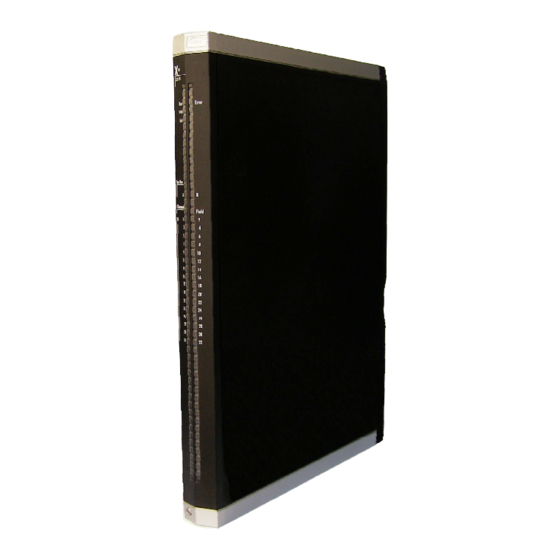
HIMA HIMax X-DI 32 04 Manual (56 pages)
Digital Input Module with Sequence of Events Recording
Brand:
HIMA
| Category:
I/O Systems
| Size: 3 MB
Table of Contents
Table of Contents
3
Introduction
5
Structure and Use of this Manual
5
Target Audience
5
Table 1: Additional Relevant Manuals
5
Formatting Conventions
6
Safety Notes
6
Operating Tips
7
Safety
8
Intended Use
8
Environmental Requirements
8
ESD Protective Measures
8
Table 2: Environmental Requirements
8
Residual Risk
9
Safety Precautions
9
Emergency Information
9
Product Description
10
Safety Function
10
Reaction in the Event of a Fault
10
Scope of Delivery
10
Type Label
11
Figure 1: Sample Type Label
11
Structure
12
Block Diagram
12
Figure 2: Block Diagram
12
Indicators
13
Figure 3: Indicators
13
Module Status Indicators
14
Table 3: Blinking Frequencies of Leds
14
Table 4: Module Status Indicators
14
System Bus Indicators
15
I/O Indicators
15
Table 5: System Bus Indicators
15
Table 6: I/O Indicators Leds
15
Product Data
16
Figure 4: Views
16
Table 7: Product Data
16
Table 8: Specifications for the Digital Inputs
17
Table 9: Product Data for Supply
17
Connector Boards
18
Mechanical Coding of Connector Boards
18
Table 10: Available Connector Boards
18
Coding of X-CB 015 Connector Boards
19
Figure 5: Coding Example
19
Table 11: Position of Coding Wedges
19
Connector Boards with Screw Terminals
20
Figure 6: X-CB 015 Connector Boards with Screw Terminals
20
Terminal Assignment for Connector Boards with Screw Terminals
21
Table 12: Terminal Assignment for Connector Boards with Screw Terminals
21
Table 13: Cable Plug Properties
22
Pin Assignment for Connector Boards with Cable Plug
23
Figure 7: X-CB 015 Connector Boards with Cable Plug
23
Pin Assignment for Connector Boards with Cable Plug
24
Table 14: Pin Assignment for Connector Boards with Cable Plug
24
System Cable X-CA 001
25
Figure 8: System Cable X-CA 001 01 N
25
Table 15: Cable Data
25
Table 16: Available System Cables
25
Cable Plug Coding
26
Start-Up
27
Mounting
27
Wiring Inputs Not in Use
27
Mounting and Removing the Module
28
Mounting a Connector Board
28
Figure 9: Inserting the Connector Board
28
Figure 10: Securing the Connector Board with Captive Screws
29
Mounting and Removing the Module
30
Figure 11: Mounting and Removing a Module
31
Sequence of Events Recording (SOE)
32
Table 17: Event Description
32
Configuring the Module in Silworx
33
Tab: Module
34
Table 18: Module Tab in the Hardware Editor
34
Tab: I/O Submodule DI32_04
35
Table 19: Tab I/O Submodule DI32_04 in the Hardware Editor
35
Tab: I/O Submodule DI32_04: Channels
36
Table 20: Tab I/O Submodule D32_04: Channels in the Hardware Editor
36
Submodule Status [DWORD]
37
Table 21: Submodule Status [DWORD]
37
Diagnostic Status [DWORD]
38
Table 22: Diagnostic Information [DWORD]
38
Connection Variants
39
Input Wiring
39
Figure 12: Wiring with Contact Maker or Two-Wire Proximity Switch
39
Figure 13: Wiring with Three-Wire Proximity Switches
39
Figure 14: Wiring of a Digital Signal Source with Electrically Isolated Supply
40
Figure 15: Wiring of a Digital Signal Source with Non-Electrically Isolated Supply
40
Figure 16: Redundant Wiring with Contact Maker or Two-Wire Proximity Switch
41
Figure 17: Redundant Wiring with Three-Wire Proximity Switch
41
Figure 18: Redundant Wiring of a Digital Signal Source with Electrically Isolated Supply
42
Wiring Transmitters Via Field Termination Assembly
43
Ex-Protection with Zener Barriers
43
Figure 19: Connection Via Field Termination Assembly
43
Figure 20: Single-Channel Proximity Switch Connection with Barriers
43
Ex-Protection with Isolation Amplifier
44
Figure 21: Single-Channel Connection of an Isolation Amplifier
44
Operation
45
Handling
45
Diagnosis
45
Maintenance
46
Maintenance Measures
46
Loading the Operating System
46
Proof Test
46
Decommissioning
47
Transport
48
Disposal
49
Appendix
50
Glossary
50
Index of Figures
51
Index of Tables
52
Index
53
Advertisement
Advertisement
Related Products
HIMA HIMax X-DI 16 01
HIMA HIMax X-DI 32 03
HIMA HIMax X-DO 32 01
HIMA X-AI 32 01
HIMA X-AI 32 51
HIMA HIMax X-AO 16 01
HIMA HIMax X-DO 24 01
HIMA HIMax X-AI 16 51
HIMA HIMax X-AO 16 51
HIMA HIMax X-DI 32 02
HIMA Categories
Controller
Control Unit
I/O Systems
Industrial Equipment
Computer Hardware
More HIMA Manuals
Login
Sign In
OR
Sign in with Facebook
Sign in with Google
Upload manual
Upload from disk
Upload from URL