Sign In
Upload
Manuals
Brands
hilscher Manuals
Motherboard
NXHX 4000-JTAG+
hilscher NXHX 4000-JTAG+ Manuals
Manuals and User Guides for hilscher NXHX 4000-JTAG+. We have
1
hilscher NXHX 4000-JTAG+ manual available for free PDF download: Device Description
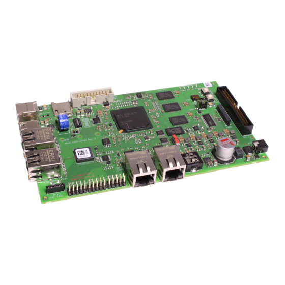
hilscher NXHX 4000-JTAG+ Device Description (70 pages)
Brand:
hilscher
| Category:
Motherboard
| Size: 6 MB
Table of Contents
Development Board
2
Table of Contents
2
1 Introduction
4
About this Document
4
Description of the Contents
4
List of Revisions
4
Conventions in this Document
4
Reference to Hardware
4
Table 1: List of Revisions
4
Table 2: Reference to Hardware
4
Legal Notes
5
2 Descriptions and Drawings
9
Key Features
9
Overview
11
Block Diagram
11
Figure 1: NXHX 4000-JTAG+ Block Diagram
11
Positions of Interfaces and Operating Elements
12
Figure 2: Positions on NXHX 4000-JTAG+ Board (View from Top)
12
Figure 3: Bottom View NXHX 4000-JTAG
12
Table 3: Positions on Printed Circuit Board
13
Operating Elements
14
S300 - DIP Switches for Selecting Boot Mode and PLL Clock Speed
14
Table 4: Functions of the S300 DIP Switches
15
Table 5: S300 Boot Mode Configuration
16
Table 6: S300 Boot Sequence Configuration
16
S301 - DIP Switches for User-Defined Inputs
17
T300 - Power-On Reset Push Button
17
T301 - Reset Push Button
17
Table 7: S301 for User-Defined Inputs
17
Table 8: T300 - Power-On-Reset Button
17
Table 9: T301 - Reset Button
17
S1300 - Slide Switch for SDRAM/SPM Selection at Host Interface
18
Table 10: S1300 Switch for SDRAM/SPM Selection
18
Interfaces
19
X300 - JTAG Connector
19
X301 - USB 1.1 Device Connector ("Mini-B" Jack)
19
Table 11: Pin Assignments JTAG Connector
19
Table 12: Pin Assignments of Mini-B USB Connector
19
X800 - USB 2.0 Host Connector ("Type A" Jack)
20
X801 - USB 2.0 Device Connector ("Type B" Jack)
20
X1000/X1100 - Gigabit Ethernet Connectors
20
Table 13: Pin Assignments of USB 2.0 Host Connector
20
Table 14: Pin Assignments USB 2.0 Device Connector
20
Table 15: Gigabit Ethernet RJ45 Pin Assignment
20
X1200 - Microsd Card Reader
21
Table 16: Pin Assignment X1200
21
X1300 - Host Interface Connector
22
Table 17: Pin Assignment of X1300 HIF Connector
22
X1400/X1401 - Real-Time Ethernet Connectors
23
Table 18: Ethernet RJ45 Pin Assignment
23
X1600 - Connector for NXHX-RS232 and NXHX Fieldbus Adapter Modules
24
Table 19: Pin Assignment X1600
24
Table 20: Pin Assignment X1601
25
X1602 - Connector for NXHX Fieldbus Adapter Modules
26
Table 21: Pin Assignment X1602
26
X1603 - Connector Socket for AIFX Detached Fieldbus Interface Modules
27
Table 22: Pin Assignment X1603
27
X1800 - Interface Connector
28
Table 23: Pin Assignments Display Connector
28
X2200 - Connector for +24 V DC Power Supply
29
Table 24: Pin Assignment Power Supply Socket
29
Leds
30
Sys Led
30
COM Leds
30
Table 25: Pinning of SYS LED
30
Table 26: System Status LED
30
Table 27: COM Leds on the NXHX 4000-JTAG+ Board
30
Leds on RJ45 Real-Time Ethernet Jacks
31
Table 28: RJ45 Ethernet Leds on NXHX 4000-JTAG+ Board
31
Leds on RJ45 Gigabit Ethernet Jacks
32
User-Definable Leds
32
Table 29: RJ45 Gigabit Ethernet Leds on the NXHX 4000-JTAG+ Board
32
Table 30: User-Definable Leds on the NXHX 4000-JTAG+ Board
32
Matrix Label
33
Figure 4: Matrix Label NXHX 4000-JTAG
33
3 Accessories
34
NXHX-RS232: Serial Interface Adapter
34
Table 31: NXHX-RS Technical Data
34
Table 32: RS-232 Pin Assignment D-Sub
34
NXHX-FTDI: Serial Dual-Port Memory Via USB Device at Host Interface
35
Figure 5: NXHX-FTDI Printed Circuit Board
35
Table 33: Positions in Figure
35
Table 34: Technical Data NXHX-FTDI Device
35
Table 35: Pinning Host Interface X400 of NXHX-FTDI Device
36
Table 36: Pinning of USB Interface
36
NXHX Fieldbus Interface Adapter Modules
38
Overview
38
Figure 6: Fieldbus Connector (Dimensions in MM)
38
Table 37: Pins of Connector to NXHX Fieldbus Adapter
38
Nxhx-Dp
39
Nxhx-Co
39
Table 38: NXHX-DP Technical Data
39
Table 39: PROFIBUS Pin Assignment on NXHX-DP
39
Table 40: NXHX-CO Technical Data
39
Nxhx-Dn
40
Nxhx-CC
40
AIFX Detached Fieldbus Interface Devices
41
Overview
41
Aifx-Dp
41
Aifx-Co
42
Aifx-Dn
42
Aifx-CC
43
4 Technical Data NXHX 4000-JTAG
44
5 Schematic Diagrams
45
Jtag_Reset_Rdy_Run
46
Figure 7: "JTAG_RESET_RDY_RUN" Schematic Diagram
46
Debugging
47
Figure 8: "Debugging" Schematic Diagram
47
Ddr3_Netx
48
Figure 9: "DDR3_NETX" Schematic Diagram
48
Ddr3_Chip1
49
Figure 10: "DDR3_CHIP1" Schematic Diagram
49
Ddr3_Chip2
50
Figure 11: "DDR3_CHIP2" Schematic Diagram
50
Ddr3_Chipecc
51
Figure 12: "DDR3_CHIPECC" Schematic Diagram
51
Usb 2.0
52
Figure 13: "USB 2.0" Schematic Diagram
52
Rgmii_Netx_Thermal
53
Figure 14: "RGMII_NETX_THERMAL" Schematic Diagram
53
Rgmii_Phy1
54
Figure 15: "RGMII_PHY1" Schematic Diagram
54
Rgmii_Phy2
55
Figure 16: "RGMII_PHY2" Schematic Diagram
55
I2C_Rtc_Microsd
56
Figure 17: "I2C_RTC_MICROSD" Schematic Diagram
56
Sdram_Spm
57
Figure 18: "SDRAM_SPM" Schematic Diagram
57
Rte
58
Figure 19: "RTE" Schematic Diagram
58
Lvds
59
Figure 20: "LVDS" Schematic Diagram
59
Mmio_Fiberoptic
60
Figure 21: "MMIO_FIBEROPTIC" Schematic Diagram
60
Minipciexpress
61
Figure 22: "MINIPCIEXPRESS" Schematic Diagram
61
Rgb
62
Figure 23: "RGB" Schematic Diagram
62
Power
63
Figure 24: "POWER" Schematic Diagram
63
Power_Supply_1
64
Figure 25: "POWER_SUPPLY_1" Schematic Diagram
64
Power_Supply_2
65
Figure 26: "POWER_SUPPLY_2" Schematic Diagram
65
Power_Supply_3
66
Figure 27: "POWER_SUPPLY_3" Schematic Diagram
66
List of Figures
67
Contacts
70
Advertisement
Advertisement
Related Products
hilscher NXHX 51-ETM
hilscher NXHX 90-JTAG
hilscher NXHX 52-JTAG
hilscher NXHX 90-MC
hilscher 7763.200
hilscher netSHIELD NSHIELD 90-RE
hilscher Categories
Gateway
Computer Hardware
Network Hardware
Motherboard
PCI Card
More hilscher Manuals
Login
Sign In
OR
Sign in with Facebook
Sign in with Google
Upload manual
Upload from disk
Upload from URL