Sign In
Upload
Manuals
Brands
hilscher Manuals
Measuring Instruments
NANL-B500G-RE
hilscher NANL-B500G-RE Ethernet Analyzer Manuals
Manuals and User Guides for hilscher NANL-B500G-RE Ethernet Analyzer. We have
2
hilscher NANL-B500G-RE Ethernet Analyzer manuals available for free PDF download: User Manual
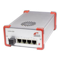
hilscher NANL-B500G-RE User Manual (90 pages)
netANALYZER device
Brand:
hilscher
| Category:
Measuring Instruments
| Size: 2.73 MB
Table of Contents
User Manual Netanalyzer Device Nanl-B500G-Re
2
Table of Contents
2
1 Introduction
5
About the User Manual
5
Obligation to Read and Understand the Manual
5
List of Revisions
6
Table 1: List of Revisions
6
Conventions in this Manual
7
Product DVD and Documentation
8
Hardware, Firmware and Driver Versions
8
Table 2: Netanalyzer Hardware
8
Table 3: Installed Netanalyzer Files (Firmware, Driver, Toolkit)
8
Legal Notes
9
Registered Trademarks
12
Licenses
13
Table 4: Required Licenses for "Autonomous Operating Mode" and "Snapshot Mode
13
2 Safety
14
General Note
14
Intended Use
14
Personnel Qualification
14
Table 5: Netanalyzer Device
14
Property Damage
15
Exceeding Permissible Supply Voltage
15
Exceeding Permissible Signaling Voltage
15
Exceeding the Permissible Current Consumption at the External I/O Interface
16
Damage of Externally Attached Hardware
16
Assignment of Wrong IP Addresses, Malfunction (NANL-B500G-RE)
17
Power Drop During Write and Delete Accesses in the File System
17
Exceeding the Maximum Number of Permitted Write and Delete Accesses
17
Labeling of Safety Messages
18
References Safety
18
Table 6: Singal Words
18
Table 7: Safety Signs
18
3 Description
19
Recording and Analyzing Data Traffic
20
Figure 1: Typical Application (Use Case 2) - the Communication between a Device and Its Connection Partners in a Network Should be Analyzed
20
Figure 2: Example Representation Physical TAP
20
Figure 3: Typical Analyzer Application with the Capturing of the Ethernet Data Transfer and IO Events
21
Table 8: TAP Delay
21
Interactive and Autonomous Operating Mode
22
Figure 4: Interactive and Autonomous Operating Mode
22
4 System Requirements
23
Hardware Requirements
23
Power Supply and Host Interface
24
Maximum Permissible Current Consumption (External IO Interface)
24
Table 9: Requirements Power Supply and Host Interface NANL-B500G-RE
24
Table 10: Maximum Permissible Current Consumption (External IO Interface NANL-B500G- RE)
24
Requirements NANL-B500G-RE (Autonomous Operating Mode)
25
5 Getting Started
26
Notes for Installation and Operation
26
Overview Installation
27
Table 11: Notes about Installation and Operation
27
Table 12: Overview Installation
27
Overview Installation Update
28
Table 13: Overview How to Update the Installation
28
Property Damage Messages
29
Exceeding Permissible Supply Voltage
29
Exceeding Permissible Signaling Voltage
29
Exceeding the Permissible Current Consumption at the External I/O Interface
29
Damage of Externally Attached Hardware
30
Assignment of Wrong IP Addresses, Malfunction (NANL-B500G-RE)
30
Power Drop During Write and Delete Accesses in the File System
31
Configure IP Address
32
6 Device Drawings
34
Analyzer Device NANL-B500G-RE
34
Figure 5: Front Side Analyzer Device NANL-B500G-RE
34
Figure 6: Reverse Side Analyzer Device NANL-B500G-RE
34
Table 14: Explanations to the Front Side and Reverse Side NANL-B500G-RE
34
7 Commissioning
35
Check Firewall Settings
35
Figure 7: Firewall Settings
35
Table 15: Workarround if Firewall Blocks Communication
35
Netanalyzer Configuration Page
36
Figure 8: Netanalyzer Configuration Page
36
Table 16: Netanalyzer Configuration Page
36
Interactive Operating Mode, Connection to PC
38
Autonomous Operating Mode, General Conditions and Requirements
39
PCAP Files (File Name and Size)
40
Requirements for Using the Autonomous Operating Mode
40
Default Settings for the Behavior of the GPIO Signals in "Live Dump Mode
41
Set the Time for the Autonomous Operating Mode
42
Figure 9: Website Netanalyzer Configuration
43
Estimate Required USB Memory Capacity for Snapshot Mode Theoretically
44
Figure 10: Schematic Representation of the Reserve Capacity of the USB Memory Device with a Maximum Number of Snapshots = "4
44
Set Maximum Number of Snapshots for Autonomous Operating Mode
46
Figure 11: Website Netanalyzer Configuration
47
Starting or Stopping NANL-B500G-RE in the Autonomous Operating Mode
48
Autonomous Operating Mode, Capturing on USB Memory Device
49
Full Capturing Process (Live-Dump-Mode)
49
Capturing Snapshots (Snapshot Mode)
51
Displaying Lost Frames in Wireshark
53
Figure 12: Buffer Overflow
53
Inserting Netanalyzer Hardware into the Communication Link
55
Application Case 1
56
Application Case 2
56
Figure 13: Application Case 1
56
Application Case 3
57
Figure 14: Application Case 2
57
Application Case 4
58
Figure 15: Application Case 3
58
Figure 16: Application Case 4 - Recording of the Runtime in the Device
60
Data Load Limitation
61
Auto-Crossover and Port-Switching
62
Figure 17: Example - Auto-Crossover and Port-Switching
62
Figure 18: Design of a TAP, at the Right Side Ports of Device 1 and Device 2 Exchanged
62
How to Update the NANL-B500G-RE Firmware
63
How to Update the NANL-B500G-RE Firmware Using a Web Browser
63
Figure 19: Ethernet Device Configuration - NANL-B500G-RE Found (Example)
64
How to Update the NANL-B500G-RE Firmware Via FTP
66
Figure 20: Ethernet Device Configuration - NANL-B500G-RE Found (Example)
66
Figure 21: FTP Server Log on Screen
67
Figure 22: Copy the Firmware Update File to the Netanalyzer FTP Server Directory
67
Figure 23: Netanalyzer FTP Server Directory Containing the Firmware Update File
68
Temperature Control of the Fan (NANL- B500G-RE)
69
Table 17: Threshold for the Temperature Control of the Fan
69
8 Hardware Properties
70
Timestamp
71
Figure 24: Ethernet Frame Timestamp-Point for „Ethernet Mode" and „Transparent Mode
71
Transparent Mode
72
Figure 25: Basic Principle of an Ethernet Frame in the Ethernet Mode or in the Transparent Mode
72
Figure 26: Ethernet Frame in Wireshark in the Ethernet Mode
72
Figure 27: Ethernet Frame in Wireshark in the Transparent Mode
72
9 Troubleshooting
73
10 Leds
75
Leds NANL-B500G-RE
75
SYS, STA0, STA1, I/O, LINK and RX (Front Side)
75
Table 18: Leds NANL-B500G-RE (Front Side), Interactive Operating Mode and Autonomous Operating Mode
77
Table 19: Indicator States
77
LINK-ACT and LINK-1000/LINK100 (Reverse Side)
78
Table 20: Leds NANL-B500G-RE (Reverse Side)
78
11 Connectors and Interfaces
79
Power Supply NANL-B500G-RE
79
Ethernet Interface
80
Ethernet Pinning at the RJ45 Socket
80
Data of the Ethernet Connection
80
Figure 28: Ethernet Pinning at the RJ45 Socket
80
Table 21: Ethernet Pinning at the RJ45 Socket
80
Table 22: Data of the Ethernet Connection
80
External IO Interface
81
Connection Cable for External IO Interface
81
Figure 29: Male Connector External IO Interface
81
Table 23: Pin out External IO Interface
81
Table 24: Requirements for the Connection Cable for External IO Interface
81
Characteristics of the Input Signal at the I / O Interface
82
Figure 30: Behavior of the Input Voltage, Examples Flank Rise: Left - Steep (Desired), Right - Flat (Not Desired)
82
Figure 31: Equivalent Circuit Diagram NANL-B500G-RE
82
Table 25: Low and High Voltage Thresholds for NANL-B500G-RE
82
12 Technical Data
83
Analyzer Device NANL-B500G-RE
83
Table 26: Technical Data Analyzer Device NANL-B500G-RE
83
13 Annex
86
Disposal of Waste Electronic Equipment
86
List of Figures
87
Glossary
89
Contacts
90
Advertisement
hilscher NANL-B500G-RE User Manual (80 pages)
netANALYZER devices
Brand:
hilscher
| Category:
Measuring Instruments
| Size: 3.15 MB
Table of Contents
User Manual Netanalyzer Devices
2
Table of Contents
2
1 Introduction
5
About the User Manual
5
List of Revisions
5
Table 1: List of Revisions
5
Hardware, Firmware and Driver Versions
6
Table 2: Netanalyzer Hardware
6
Table 3: Installed Netanalyzer Files (Firmware, Driver, Toolkit)
6
Conventions in this Manual
7
Installation DVD and Documentation
8
Table 4: Important Installation Components on the DVD
8
Legal Notes
9
Copyright
9
Important Notes
9
Exclusion of Liability
10
Warranty
10
Export Regulations
11
Registered Trademarks
11
Licenses
11
Obligation to Read and Understand the Manual
11
2 Safety
12
General Note
12
Intended Use
12
Personnel Qualification
12
Table 5: Netanalyzer Devices
12
Safety Instructions to Avoid Personal Injury
13
Electrical Shock Hazard (NANL-C500-RE)
13
Safety Instructions to Avoid Property Damage
14
Device Destruction by Exceeding Allowed Supply Voltage
14
Device Destruction by Exceeding Allowed Signaling Voltage
14
Device Destruction by Exceeding Allowed External IO Interface Output Current
15
Damage of Externally Attached Hardware
15
Electrostatically Sensitive Devices (NANL-C500-RE)
16
Assignment of Wrong IP Addresses, Malfunction (NANL-B500G-RE)
16
References Safety
16
Labeling of Safety Messages
17
Table 6: Signal Words and Safety Signs in Safety Messages on Property Damage
17
Table 7: Safety Signs in Safety Messages on Personal Injury
17
Table 8: Signal Words in Safety Messages on Property Damage
17
Table 9: Safety Signs for Warning of Property Damage
17
3 Description
18
Recording and Analyzing Data Traffic
19
Figure 1: Typical Application (Use Case 2) - the Communication between a Device and Its Connection Partners in a Network Should be Analyzed
19
Figure 2: Example Representation Physical TAP
19
Figure 3: Typical Analyzer Application with the Capturing of the Ethernet Data Transfer
20
Interactive and Autonomous Operating Mode
21
Figure 4: Interactive and Autonomous Operating Mode
21
4 System Requirements
22
Hardware Requirements
22
Power Supply and Host Interface
23
Table 10: Requirements Power Supply and Host Interface for NANL-C500-RE or NANL- B500G-RE
23
Maximum Permissible Output Current (External IO Interface)
24
Table 11: Maximum Permissible Output Current (External IO Interface NANL-C500-RE)
24
Table 12: Maximum Permissible Output Current (External IO Interface NANL-B500G-RE)
24
Requirements NANL-B500G-RE (Autonomous Operating Mode)
25
5 Getting Started
26
Notes for Installation and Operation
26
Overview Installation
27
Table 13: Notes about Installation and Operation
27
Table 14: Overview Installation
27
Overview Installation Update
28
Table 15: Overview How to Update the Installation
28
Configuring the NANL-B500G-RE IP Address
29
Autonomous Operating Mode for NANL-B500G-RE
31
Set the Time for the Autonomous Operating Mode
33
Figure 5: Website Netanalyzer Configuration
34
Displaying Lost Frames in Wireshark
35
Figure 6: Buffer Overflow
35
6 Device Drawings
37
Analyzer Card NANL-C500-RE
37
Figure 7: Top Side Analyzer Card NANL-C500-RE
37
Figure 8: Slot Plate Analyzer Card NANL-C500-RE
37
Analyzer Device NANL-B500G-RE
38
Figure 9: Front Side Analyzer Device NANL-B500G-RE
38
Figure 10: Reverse Side Analyzer Device NANL-B500G-RE
38
Table 16: Explanations to the Front Side and Reverse Side NANL-B500G-RE
38
7 Hardware Installation and Operation
39
Safety Messages on Personal Injury
39
Electrical Shock Hazard (NANL-C500-RE)
39
Property Damage Messages
40
Device Destruction by Exceeding Allowed Supply Voltage
40
Device Destruction by Exceeding Allowed Signaling Voltage
40
Device Destruction by Exceeding Permissible External IO Interface Output Current
41
Damage of Externally Attached Hardware
41
Electrostatically Sensitive Devices (NANL-C500-RE)
42
Assignment of Wrong IP Addresses, Malfunction (NANL-B500G-RE)
42
Mounting Analyzer Card NANL-C500-RE to the PC
43
Connecting Analyzer Device NANL-B500G-RE to the PC (Interactive Opeating Mode)
44
Connecting Analyzer Device NANL-B500G-RE to USB (Autonomous Operating Mode)
45
Inserting Netanalyzer Hardware into the Communication Link
47
Application Case 1
48
Application Case 2
48
Figure 11: Application Case 1
48
Application Case 3
49
Figure 12: Application Case 2
49
Application Case 4
50
Figure 13: Application Case 3
50
Application Case 4
51
Figure 14: Application Case 4 - Recording of the Runtime in the Device
52
Auto-Crossover and Port-Switching
53
Figure 15: Example - Auto-Crossover and Port-Switching
53
Figure 16: Design of a TAP, at the Right Side Ports of Device 1 and Device 2 Exchanged
53
How to Update the NANL-B500G-RE Firmware
54
Figure 17: Ethernet Device Configuration - NANL-B500G-RE Found (Example)
54
Figure 18: FTP Server Log on Screen
55
Figure 19: Copy the Firmware Update File to the Netanalyzer FTP Server Directory
55
Figure 20: Netanalyzer FTP Server Directory Containing the Firmware Update File
55
Temperature Control of the Fan (NANL- B500G-RE)
56
Demounting Analyzer Card NANL-C500-RE
57
8 Hardware Properties
58
Timestamp
59
Figure 21: Message Timestamp-Point for „Ethernet Mode" and „Transparent Mode
59
Transparent Mode
60
Figure 22: Basic Principle of an Ethernet Frame in the Standard Ethernet Mode or in the Transparent Mode
60
Figure 23: Ethernet Telegram (Ethernet Frame) in Wireshark in the Standard Ethernet Mode
60
Figure 24: Ethernet Telegram (Ethernet Frame) in Wireshark in the Transparent Mode
60
9 Troubleshooting
61
10 Leds
62
Leds NANL-C500-RE
62
Table 17: Leds NANL-C500-RE
62
Table 18: Indicator States
62
Leds NANL-B500G-RE
63
SYS, STA0, STA1, I/O, LINK and RX (Front Side)
63
Table 19: Leds NANL-B500G-RE (Front Side), Interactive Operating Mode and Autonomous Operating Mode
64
Table 20: Indicator States
64
LINK-ACT and LINK-1000/LINK100 (Reverse Side)
65
Table 21: Leds NANL-B500G-RE (Reverse Side)
65
11 Connections and Interfaces
66
Power Supply NANL-B500G-RE
66
Ethernet Interface
67
Ethernet Pinning at the RJ45 Socket
67
Data of the Ethernet Connection
67
Figure 25: Ethernet Pinning at the RJ45 Socket
67
Table 22: Ethernet Pinning at the RJ45 Socket
67
Table 23: Data of the Ethernet Connection
67
External IO Interface
68
Connection Cable for External IO Interface
68
Figure 26: Male Connector External IO Interface
68
Table 24: Pin out External IO Interface
68
Table 25: Requirements for the Connection Cable for External IO Interface
68
12 Technical Data
69
Analyzer Card NANL-C500-RE
69
Table 26: Technical Data Analyzer Card NANL-C500-RE
69
Analyzer Device NANL-B500G-RE
71
Table 27: Technical Data Analyzer Device NANL-B500G-RE
71
13 Annex
73
Hardware Update for NXANL 500-RE Rev 2 and Rev 3
73
Failure in 10 Mbit/S Half Duplex Mode and Workaround
75
Disposal of Waste Electronic Equipment
76
List of Figures
77
List of Tables
78
Glossary
79
Contacts
80
Advertisement
Related Products
hilscher NANL-C500-RE
hilscher netPI NOIT-E-NPI3-51-EN-RE
hilscher NIOT-E-TIB100-GB-RE
hilscher netX 90
hilscher netX 51
hilscher NIOT-E-NPIX-EVA
hilscher NIOT-E-NPIX-RS232
hilscher NHST-T100-EN
hilscher netFIELD
hilscher NFD-3090-ECS-IOLM/W
hilscher Categories
Gateway
Computer Hardware
Network Hardware
Motherboard
PCI Card
More hilscher Manuals
Login
Sign In
OR
Sign in with Facebook
Sign in with Google
Upload manual
Upload from disk
Upload from URL