Sign In
Upload
Manuals
Brands
Helios Manuals
Measuring Instruments
PD2-6400
Helios PD2-6400 Manuals
Manuals and User Guides for Helios PD2-6400. We have
1
Helios PD2-6400 manual available for free PDF download: Instruction Manual
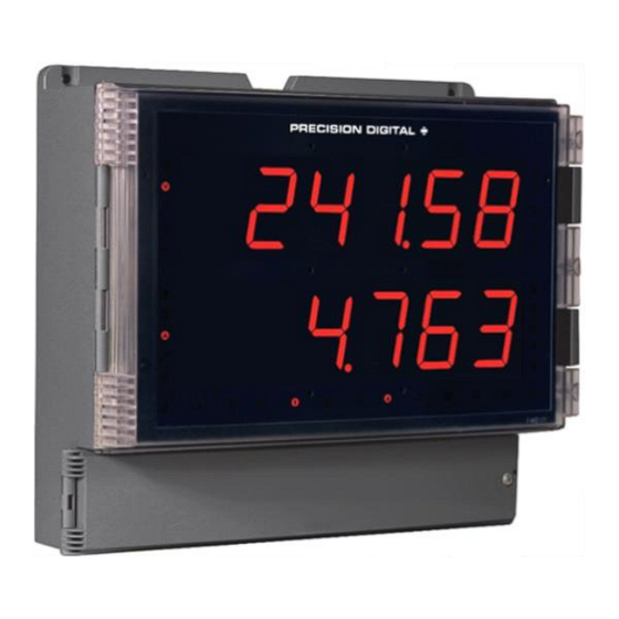
Helios PD2-6400 Instruction Manual (49 pages)
High Voltage & High Current Meter
Brand:
Helios
| Category:
Measuring Instruments
| Size: 3.55 MB
Table of Contents
Table of Contents
3
Introduction
6
Ordering Information
6
Specifications
8
General
8
Voltage and Current Inputs
9
Relays
9
USB Connection
9
Isolated 4-20 Ma Transmitter Output
10
RS-485 Serial Communications
10
Modbus ® RTU Serial Communications
10
Digital Input (F4)
10
Digital Inputs & Outputs
10
Meterview Pro Software
10
Compliance Information
11
Safety
11
Safety Information
11
Installation
11
Unpacking
11
Wall Mounting Instructions
12
Mounting Dimensions
12
Conduit Holes Location
12
Figure 1. Meter Mounting Holes Location
12
Figure 2. Meter Mounting Holes Dimensions
12
Figure 3. Meter Dimensions - Side View
12
Figure 4. Meter Dimensions - Front View
12
Figure 5. Conduit Holes Location - Bottom View
12
Pipe Mounting Instructions
13
Figure 6. Vertical Pipe Mount Assembly
13
Figure 7. Horizontal Pipe Mount Assembly
13
Installation Overview
14
Meterview Pro Software
14
Meterview Pro Installation
14
Connections
15
Connectors Labeling
15
Figure 8. PD2-6400-6H0 / 7H0 Connectors Label
15
Figure 9. PD2-6400-6H7 / 7H7 Connectors Label
15
Power Connections
16
Signal Connections
16
Figure 10. Power Connections
16
Figure 11. AC Voltage Input Connection
16
Figure 12. DC Voltage Input Connections
16
Figure 13. AC Current Connections
16
Figure 14. AC Current Transformer Connections
16
Figure 15. DC Current Connections
16
Relay Connections
17
Figure 16. AC Current and Voltage Connections
17
Figure 17. AC Current Transformer and Voltage Connections
17
Figure 18. DC Current and Voltage Connections
17
Figure 19. Relay Connections
17
Switching Inductive Loads
18
RS-485 Connections
18
RS-485 Multi-Drop Connection
18
RS-485 Serial Converters
18
Figure 20. AC and DC Loads Protection
18
Figure 21. Low Voltage DC Loads Protection
18
Figure 22. RS-485 Connection
18
Digital I/O Connections
19
Figure 23. Five-Wire RS-485 Connections
19
Figure 24. Three-Wire RS-485 Multi-Drop Connections
19
Figure 25. Connections for RS-485 Connector to Serial Converter
19
Figure 26. Three-Wire RS-485 Connection
19
Figure 27. Digital Input and Output Connections
19
F4 Digital Input Connections
20
4-20 Ma Output Connections
20
Analog Output Transmitter Power Supply
20
Remote Operation of Meter
20
Interlock Relay Feature
20
Figure 28. F4 Digital Input Connections
20
Figure 29. 4-20 Ma Output Connections
20
Figure 30. Analog Output Supply Powering Other Devices
20
Figure 31. Meter to PDA2364-MRUE Control Station Connection
20
Figure 32. Interlock Connections
20
Setup and Programming
21
Overview
21
LED Status Indicators
21
Programming Buttons
22
Display Functions & Messages
23
Main Menu
24
Setting Numeric Values
25
Setting up the Meter (Setup)
25
Setting the Decimal Point (Dec Pt)
25
Setting the Input Calibration (Incal)
26
Setting the Display Parameter & Intensity (Dsplay)
28
Display Intensity (D-Inty)
28
Setting the Input Units or Custom Tags (Units)
29
Setting the Relay Operation (Relay)
29
Setting the Relay Assignment (Assign)
30
Setting the Relay Action
30
Programming Set and Reset Points
30
Setting Fail-Safe Operation
30
Programming Time Delay
30
Relay and Alarm Operation Diagrams
31
High Alarm Operation (Set > Reset)
31
Low Alarm Operation (Set < Reset)
31
High Alarm with Fail-Safe Operation (Set > Reset)
31
Low Alarm with Fail-Safe Operation (Set < Reset)
31
Time Delay Operation
32
Relay Operation Details
33
Overview
33
Relays Auto Initialization
33
Fail-Safe Operation
33
Front Panel Leds
33
Latching and Non-Latching Relay Operation
33
Non-Latching Relay (Auto)
34
Non-Latching Relay with Manual Reset (A-Nman)
34
Latching Relay (Latch)
34
Latching Relay with Clear (Lt-Clr)
34
Acknowledging Relays
35
Pump Alternation Control Applications (Altern)
35
Setting up the Interlock Relay (Force On) Feature
35
Scaling the 4-20 Ma Analog Output (Aout)
36
Reset Menu (Reset)
36
Manual Control Menu (Contrl)
36
Setting up the Password (Pass)
37
Protecting or Locking the Meter
37
Making Changes to a Password Protected Meter
37
Disabling Password Protection
37
Advanced Features Menu
38
Advanced Features Menu & Display Messages
38
Noise Filter (Filter)
39
Noise Filter Bypass (Bypass)
39
Rounding Feature (Round)
39
Modbus RTU Serial Communications (Serial)
40
Select Menu (Select)
40
Multi-Point Linearization (Linear)
40
Math Function (Nmath)
41
Math Constants (Const)
41
Low-Value Cutoff (Cutoff)
41
Analog Output Programming (Aoutpr)
41
Programmable Function Keys User Menu (User)
42
Internal Calibration (ICAL)
43
Meter Operation
44
Button Operation
44
Function Keys Operation
44
Digital Inputs Operation
44
Maximum/Minimum Readings
44
Troubleshooting
45
Diagnostics Menu (Diag)
45
Testing the Display Leds
45
Determining Software Version
45
Reset Meter to Factory Defaults
45
Factory Defaults & User Settings
46
Troubleshooting Tips
48
Advertisement
Advertisement
Related Products
Helios PD2-6100
Helios PD2-6100-6H0
Helios PD2-6100-6H7
Helios PD2-6100-7H0
Helios PD2-6100-7H7
Helios PU Series
Helios PA 24
Helios PU 24
Helios ENOVATION CONTROLS PowerVision P70
Helios PA Series
Helios Categories
Fan
Controller
Heater
Accessories
Power Supply
More Helios Manuals
Login
Sign In
OR
Sign in with Facebook
Sign in with Google
Upload manual
Upload from disk
Upload from URL