Sign In
Upload
Manuals
Brands
HEKA Manuals
Laboratory Equipment
EPC 10 USB
User Manuals: HEKA EPC 10 USB Patch Clamp Amplifier
Manuals and User Guides for HEKA EPC 10 USB Patch Clamp Amplifier. We have
1
HEKA EPC 10 USB Patch Clamp Amplifier manual available for free PDF download: User Manual
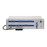
HEKA EPC 10 USB User Manual (99 pages)
Brand:
HEKA
| Category:
Laboratory Equipment
| Size: 8 MB
Table of Contents
Table of Contents
4
General Information
12
Important Safety Advice
12
Introduction
16
Introducing the EPC 10 USB
16
EPC 10 USB Patch Clamp Amplifier
16
References
17
Naming Conventions
18
MS Windows Versions
18
Macintosh
18
Description of the Hardware
20
Headstage
20
HDMI Red Star Headstage
20
EPC 10 USB HDMI Red Star Headstage
20
Main Unit
21
Front-Panel
21
EPC 10 USB Front Panel
21
Rear-Panel
23
EPC 10 USB DOUBLE, TRIPLE, and QUADRO
23
EPC 10 USB Rear Panel
23
Special Features of the EPC 10 USB
24
Timing of the AD-/DA-Channels
24
Double Staggered Acquisition Mode of the DAQ Board
24
Number of Free DA/AD Channels in EPC 10 USB Multi Amplifiers
24
Installation
26
Installing Software Only
26
Installing Hardware and Software
26
Conventions
26
Connecting the Hardware
27
Protection Key ('Dongle') Installation
28
USB Dongle Installation
28
MS Windows
28
Macos
28
Software Installation
28
Macos
29
Calibrating the Hardware
29
Exemplary Start Dialog of the Calibration Process
29
Support Hotline
30
Prompting Dialog for Shielding the Probe Inputs
30
Prompting Dialog for Connecting the Model Cell
30
Amplifier Window
32
Global Section
33
The Three Sections of the Amplifier Window
33
Global Section of the Amplifier Window
33
Tweak
34
View Tab
34
Tweak Extension of the Amplifier Window
34
View Tab of the Amplifier Window
34
Hardware Tab
35
Hardware Tab of the Amplifier Window
35
Tools Tab
37
Tools Tab of the Amplifier Window
38
Amplifier Info Dialog of the Tweak Menu
38
Compensation Tab
39
Compensation Tab of the Amplifier Window
39
Amplifier Selection
41
Amplifier Selection of an EPC 10 USB Double Amplifier
41
Amplifier Parameters
42
Amplifier Parameters of an EPC 10 USB Amplifier
42
Current Gain Ranges of the EPC 10 USB Amplifier
43
Bridge Compensation Options in Current Clamp Mode
46
Filter 1 Setting According to the Defined Series Resistance Compensation Speed
47
Verifying and Testing the EPC 10 USB
48
Testing the EPC 10 USB with the Model Circuit
48
The Model Circuit
48
SETUP" - Applying the Test Pulse
49
EPC 10 USB Double Amplifier and Test Pulse Window
49
SEAL" - Voltage Clamp Recording
51
Before C-Fast Compensation
51
After C-Fast Compensation
52
Whole-Cell" - Voltage Clamp Recording
53
Before C-Slow Compensation
53
After C-Slow Compensation
54
Whole-Cell" - Current Clamp Recording
56
Measuring the Noise of the Amplifier
58
Noise Measurement
58
Making a Full Test
59
The Full Test Is Selectable in the Tools Selection of the Amplifier Window
59
Operating Modes
62
Voltage Clamp Mode
62
Current Clamp Mode
62
Circuitry of the Voltage Clamp Mode of the EPC 10 USB
62
Current Clamp Mode
63
Circuitry of the Current Clamp Mode of the EPC 10 USB
63
Low Frequency Voltage Clamp Mode
64
Compensation Procedures
66
Series Resistance Compensation
66
Series Resistance Compensation Circuit of the EPC 10 USB
67
Capacitance Compensation
68
Maximum RS-Compensation Values
68
Offset Compensation
69
Exemplary Solutions and Their Liquid Junction Potentials
70
Patch Clamp Setup
72
Mounting the Probe
72
Ground Wires
72
Grounding the Microscope
72
External Shielding
73
Connections to Other Instruments
73
Pipette Holder and Electrode
73
Bath Electrode
74
Patch Pipettes
76
Glass Capillaries
76
Pulling
76
Coating
76
Heat Polishing
77
Use of Pipettes
77
Using the Patch Clamp
78
Forming a Seal
78
Initial Setup
78
Entering the Bath
78
Forming a Gigaseal
78
Cell-Attached Recording
79
Whole-Cell Recording
79
Breaking the Patch
79
Capacitive Transient Cancellation
80
Series Resistance Compensation
80
Current Clamp Recording
81
Low Noise Recording
82
Appendix I: Digital Inputs/Outputs
84
Digital I/O Connector
84
Pin Assignment of the Digital I/O Connector (EPC 10 USB)
84
Digital in Connector
85
Digital out Connector
85
Digital I/O Connector (40-Pin, Male) of the EPC 10 USB
85
Digital in Connector (Dsub-25, Female) of the EPC 10 USB
85
Pin Assignment of the Digital in Connector (EPC 10 USB), Upper Row
85
Pin Assignment of the Digital in Connector (EPC 10 USB), Lower Row
85
Pin Assignment of the Digital out Connector (EPC 10 USB), Upper Row
85
Breakout Cables
86
Digital out Connector (Dsub-25, Female) of the EPC 10 USB
86
Pin Assignment of the Digital out Connector (EPC 10 USB), Lower Row
86
Connecting Cables
87
DG 4/5 / Lambda 10-2 / Lambda 10-3 to EPC 10 USB
87
Dsub-25 (Male) to Dsub-25 (Female) Connecting Cable
87
Pin Assignments of Digital out Connector of EPC 10 USB and Parallel Port Connector of DG 4/5
87
Pin Assignments of Digital out Connector of EPC 10 USB and Parallel Port Connector of Lambda
88
Valvelink 8 to EPC 10 USB
89
Dsub-25 (Male) to Dsub-9 (Male) Connecting Cable
89
Pin Assignments of Digital out Connector of EPC 10 USB and Connector of Valvelink 8
89
Appendix II: Probe Adapters
90
Standard Mounting Plate
90
Standard Mounting Plate for EPC 10 USB Pre-Amplifiers
90
Dovetail Mounting Plate for EPC 10 USB Pre-Amplifiers
90
Pipette Holder SMA-Type for the S-Probe
95
Advertisement
Advertisement
Related Products
HEKA EPC 9
HEKA Falcon
HEKA Favorit-Eco 126
HEKA Favorit-Eco 126+S
HEKA Favorit-Eco 135/S
HEKA Favorit-Eco 168
HEKA Favorit-Eco 168+S
HEKA Favorit-Eco 84
HEKA Favorit-Eco 84+S
HEKA Favorit-Eco 90/S
HEKA Categories
Laboratory Equipment
Recording Equipment
Medical Equipment
More HEKA Manuals
Login
Sign In
OR
Sign in with Facebook
Sign in with Google
Upload manual
Upload from disk
Upload from URL