Sign In
Upload
Manuals
Brands
HEKA Elektronik Manuals
Amplifier
EPC 10 USB
HEKA Elektronik EPC 10 USB Manuals
Manuals and User Guides for HEKA Elektronik EPC 10 USB. We have
1
HEKA Elektronik EPC 10 USB manual available for free PDF download: Hardware Manual
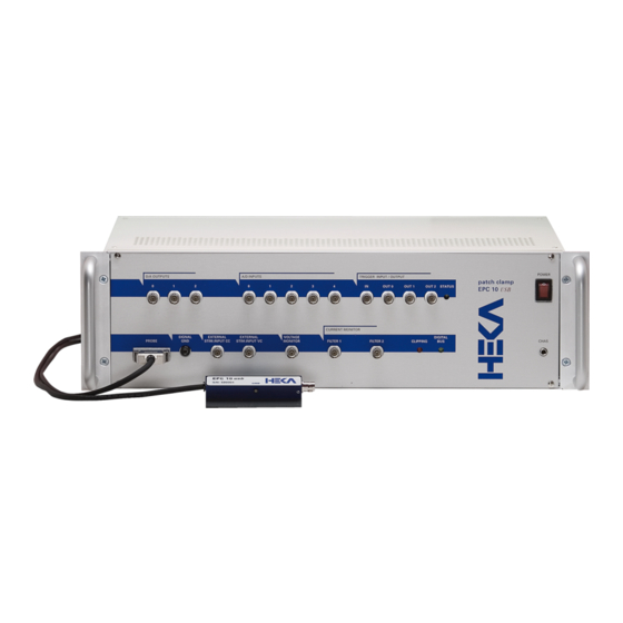
HEKA Elektronik EPC 10 USB Hardware Manual (81 pages)
Computer-controlled Patch Clamp Amplifier
Brand:
HEKA Elektronik
| Category:
Amplifier
| Size: 11 MB
Table of Contents
Table of Contents
3
1 Introduction
7
Introducing the EPC 10 USB
7
References
8
Naming Conventions
9
2 Description of the Hardware
11
Headstage
11
Red Star Headstage
11
Main Unit
12
Front-Panel
12
Rear-Panel
14
EPC 10 USB DOUBLE, TRIPLE, and QUADRO
14
Special Features of the EPC 10 USB
15
Timing of the AD-/DA-Channels
15
3 Installation
17
Installing Software Only
17
Installing Hardware and Software
17
Conventions
17
Connecting the Hardware
18
Protection Key ('Dongle') Installation
18
USB Dongle Installation
18
MS Windows
19
Macos
19
Software Installation
19
Calibrating the Hardware
20
Support Hotline
21
4 Verifying and Testing the EPC 10 USB
23
Testing the EPC 10 USB with the Model Circuit
23
The Model Circuit
23
SETUP" - Applying the Test Pulse
23
SEAL" - Voltage Clamp Recording
25
Whole-Cell" - Voltage Clamp Recording
27
Whole-Cell" - Current Clamp Recording
29
Measuring the Noise of the Amplifier
30
Making a Full Test
31
5 The Control Software
33
EPC 10 USB Window
33
Main Controls
33
Hidden Controls
40
EPC 10 USB Menu
43
Test and Calibrate Menu
43
6 Operating Modes
45
Voltage Clamp Mode
45
Current Clamp Mode
45
Low Frequency Voltage Clamp Mode
46
Search Mode
46
7 Compensation Procedures
49
Series Resistance Compensation
49
Capacitance Compensation
51
Offset Compensation
52
8 Patch Clamp Setup
55
Mounting the Probe
55
Ground Wires
55
Grounding the Microscope
55
External Shielding
55
Connections to Other Instruments
56
Pipette Holder and Electrode
56
Bath Electrode
56
9 Patch Pipettes
59
Glass Capillaries
59
Pulling
59
Coating
60
Heat Polishing
60
Use of Pipettes
60
10 Using the Patch Clamp
61
Forming a Seal
61
Initial Setup
61
Entering the Bath
61
Forming a Gigaseal
61
Cell-Attached Recording
61
Whole-Cell Recording
62
Breaking the Patch
62
Capacitive Transient Cancellation
62
Series Resistance Compensation
63
Current Clamp Recording
63
11 Low Noise Recording
65
12 Appendix I: Digital Inputs/Outputs
67
Digital I/O Connector
67
Digital in Connector
68
Digital out Connector
68
Breakout Cable
69
Connecting Cables
69
DG 4/5 / Lambda 10-2 / Lambda 10-3 to EPC 10 USB
69
Valvelink 8 to EPC 10 USB
71
13 Appendix II: Probe Adapters
73
Standard Mounting Plate
73
Dovetail Mounting Plate
73
14 Appendix III: S-Probe
75
15 Appendix IV: Pipette Holder
77
BNC-Type
77
SMA-Type
77
Advertisement
Advertisement
Related Products
HEKA Elektronik Categories
Recording Equipment
Amplifier
More HEKA Elektronik Manuals
Login
Sign In
OR
Sign in with Facebook
Sign in with Google
Upload manual
Upload from disk
Upload from URL