Table of Contents
Advertisement
Advertisement
Table of Contents

Summary of Contents for HEKA Elektronik EPC 10 USB
- Page 1 Hardware Manual Version 2.8 EPC 10 USB Computer-controlled Patch Clamp Amplifier...
- Page 2 D-67466 Lambrecht/Pfalz Email sales@heka.com Germany support@heka.com HEKA Electronic Phone +1 800 597 0580 84 October Hill Road +1 508 429 5732 01746 Holliston Web site www.heka.com Massachusetts Email sales@heka.com United States support@heka.com © 2007-2018 HEKA Elektronik Dr. Schulze GmbH COMDE1/9...
-
Page 3: Table Of Contents
4.1 Testing the EPC 10 USB with the Model Circuit ......17... - Page 4 5.1 EPC 10 USB Window ........
- Page 5 12.5.2 ValveLink 8 to EPC 10 USB ........
-
Page 7: Introduction
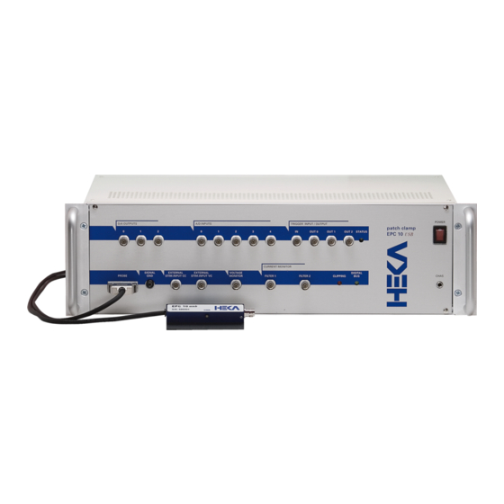
Figure 1.1: EPC 10 USB Patch Clamp amplifier The EPC 10 USB represents roughly the tenth in the series of patch clamp designs in use in the G¨ o ttingen laboratories. It is a logical successor to the classical EPC 7, retaining all of its features but adding a number of capabilities. -
Page 8: References
This manual is designed to provide a general guide for setting up and using the EPC 10 USB for experiments. It covers general information about the hardware, basic principles of the EPC 10 USB’s functions and patch clamp techniques. -
Page 9: Naming Conventions
MS Windows versions, whenever it is required. A free USB 2.0 port is required. Macintosh The EPC 10 USB USB is supported by Macintosh computers running Mac OS X 10.4 or newer. A free USB 2.0 port is required. - Page 10 Introduction http://www.heka.com...
-
Page 11: Description Of The Hardware
Figure 2.1: EPC 10 USB Red Star Headstage The probe of the EPC 10 USB is contained in a small enclosure, designed to be mounted on a micromanipulator and directly attached to the recording micropipette. It contains the sensitive amplifier that constitutes the current- to-voltage converter, as well as components for injecting signals into that amplifier. -
Page 12: Main Unit
Description of the Hardware Main Unit The main unit of the EPC 10 USB contains the power supply, the signal processing electronics, the A/D and D/A converters and the connectors for analog and digital input/output. Essentially all of the calibration adjustments are made by digital switches in the main unit, including those which depend on the properties of components in the probe. - Page 13 It is particularly useful since it will indicate clipping by internal amplifiers even in cases where, because of filtering, the output voltage is not saturated. Digital Bus: This LED lights whenever digital information is sent from the computer to the EPC 10 USB amplifier.
-
Page 14: Rear-Panel
EPC 10 USB amplifier. Trigger: This port does not exist any more. Use Trigger In on the front panel of the EPC 10 USB. USB: This port is the connection to the USB 2.0 port in the host computer, that allows the computer to commu- nicate with the EPC 10 USB. -
Page 15: Special Features Of The Epc 10 Usb
Timing of the AD-/DA-channels Figure 2.4: Double Staggered Acquisition Double Staggered Acquisition (EPC 10 USB using the LIH 8+8): The EPC 10 USB uses the double staggered acquisition mode. To support cophasic acquisition of the two most relevant signals, e.g. the current and voltage trace of the amplifier, two AD converters are used in parallel. - Page 16 Description of the Hardware http://www.heka.com...
-
Page 17: Installation
There are several possible installation procedures: 1. Software only, e.g. Patchmaster, Potmaster, Chartmaster or Fitmaster 2. EPC 10 USB and software 3. iTEV 90 USB and software 4. PG 310 USB, PG 340 USB or PG 390 USB and software 5. -
Page 18: Connecting The Hardware
flexibility for moving the Hardware from one computer system to another. 5. It is possible to “Join” two units (only for EPC 10 USB and LIH 8+8) to extend the number of analog channels controlled by one instance of the Patchmaster software. For proper synchronization of the acqui- sition clocks, a connection between the Master clock output of one unit to the Slave clock input of the other (connectors located on the rear panel) must be made using standard CAT5 patch cables. -
Page 19: Ms Windows
3.6 Software Installation 3.5.1.1 MS Windows 1. Unzip and execute the downloaded file (HASPUserSetup.exe) 2. Follow the installation instructions 3.5.1.2 MacOS 1. Unzip and open the downloaded file (Sentinel Runtime.dmg) 2. Execute Install Sentinel Runtime Environment 3. Follow the installation instructions Software Installation Now, you can install and run the Software. -
Page 20: Calibrating The Hardware
Calibration depends on temperature. We advice to let the Hardware warm up for 30-60 minutes after powering it on. The Calibration procedure can be performed with any Software. In the program, go to the Hardware menu (e.g. EPC 10 USB or PG 340 USB) Test and Calibrate Calibrate. -
Page 21: Support Hotline
ˆ Your acquisition hardware, if applicable: EPC 10 USB, LIH 8+8 ˆ Your amplifier, if applicable: EPC 10 USB, PG 310 USB ˆ The series number and version of your Hardware, if applicable: e.g. EPC 10 USB Single, serial number ’520552’, revision letter ’R’. - Page 22 Installation http://www.heka.com...
-
Page 23: Verifying And Testing The Epc 10 Usb
The following tutorial will guide you through most of the basic and some of the unique and more sophisticated features of the EPC 10 USB amplifier. At the same time it allows you to check, whether the amplifier is functioning properly. You can use the model circuit you got together with the amplifier as a substitute for a real patch clamp recording and explore the virtual ”front panel”... - Page 24 Gain or Filters. Signal display is provided by the Oscilloscope window. Figure 4.2: EPC 10 USB Amplifier and Oscilloscope dialog Put the model circuit into the ”10 M” setting, which simulates a 10 M Ω-pipette that is open to the bath solution.
-
Page 25: Seal" - Voltage Clamp Recording
10” would instruct Patchmaster to Control[: set the gain pop up in the EPC 10 USB window to the 10th value (5 mV/pA). A list of all so-called Macro Items can be output into the Notebook via the Help menu of Patchmaster. - Page 26 Verifying and Testing the EPC 10 USB In order to see the small currents resulting from the high resistance of the model circuit, set the Gain to an appropriate value by either using the Gain pop up menu (1) or by hitting the up arrow key.
-
Page 27: Whole-Cell" - Voltage Clamp Recording
4.1 Testing the EPC 10 USB with the Model Circuit The steps listed above can be automatically executed by clicking on the SEAL button or pressing the key ”2” on the numerical keypad (Amplifier Window has to be active). This will execute the following predefined protocol lines that increases the gain and then performs twice an auto-compensation - considering a possible failure in the first... - Page 28 Verifying and Testing the EPC 10 USB The peak current can be calculated from U/τ = 22 pF 5 mV /112 µs = 982 pA With the actual gain setting of 20 mV/pA this would generate a voltage of 19.6 V at the current-to-voltage converter output, which exceeds the amplifier’s voltage range.
-
Page 29: Whole-Cell" - Current Clamp Recording
Note: The 500 M Ω setting of the model circuit is not a good method for testing the fast clamp speed of the EPC 10 USB due to the long time constant of 11 ms which the amplifier can easily follow. If you want to have a better estimation of the amplifier’s speed under current clamp conditions you should... -
Page 30: Measuring The Noise Of The Amplifier
It is recommended to click the Reset button in the Amplifier window in order to reset the EPC 10 USB to its initial default configuration. Now click the Noise button (1) to start the noise test. -
Page 31: Making A Full Test
BNC connector at the probe to shield it), a 10 M Ω resistor (e.g., the model circuit) and 5 short BNC cables. In case you have an EPC 10 USB Double or Triple, select the amplifier you want to test in the EPC 10 USB amplifier dialog: 1. - Page 32 Verifying and Testing the EPC 10 USB http://www.heka.com...
-
Page 33: The Control Software
Figure 5.1: EPC 10 USB Amplifier dialog If an EPC 10 USB Double, Triple or Quadro is used, one selects the ”active” amplifier from the ”amplifier” pop up list. Only the available amplifiers can be selected in the amplifier list. When switching, Patchmaster updates all parameters to show the state of the selected amplifier. - Page 34 Clipping Indicator: A blinking box labeled ”Clip” in the Gain title indicates saturation of amplifiers in the current monitor circuitry. Like the Clipping LED on the EPC 10 USB main unit, this is a warning that excess artifacts or noise may occur due to the saturation of amplifiers.
- Page 35 R-memb: The seal resistance (R-membrane) is determined from the current sampled during the baseline and the second half of the Test Pulse. R-membrane can be encoded into a tone using the Sound feature (see below). Input ADC: The Oscilloscope can display the following signals (EPC 10 USB Single): Figure 5.5: Input ADC ˆ...
- Page 36 0 mV. The rate at which Auto V is performed is determined by the Search Mode Delay in the EPC 10 USB menu. C-fast: This is used to cancel fast capacitive currents that charge the pipette and other stray capacitances (range: 0-15 pF).
- Page 37 5.1 EPC 10 USB Window In the upper box, the total C-fast value is displayed. τ -fast determines the time constant of C-fast (up to 8 µs). The value of τ -fast may be adjusted by dragging the mouse, or typing, or automatically by selecting the Auto function.
- Page 38 Rs-compensation circuitry as the measure of series resistance. The procedure uses a routine that applies short trains of square-wave pulses (number and amplitude of these pulses are specified by the EPC 10 USB menu entry Auto C-slow Settings), averages the resulting currents and fits an exponential to deduce the com- pensation values required to cancel the current (see chapter 7 on page 43).
- Page 39 5.1 EPC 10 USB Window ˆ Bessel 100 kHz ˆ Bessel 30 kHz ˆ Bessel 10 kHz ˆ HQ 30 kHz Under most conditions a 10 kHz bandwidth is more than ample, and the filtering reduces the high-frequency noise substantially. The HQ 30 kHz setting is selected automatically when fast Rs-compensation is in use; it is of little use otherwise.
-
Page 40: Hidden Controls
It is strongly recommended to set External to ”Off” (i.e., equal to zero), if no external stimulator is connected to the ”EXT STIM.INPUT VC” on the front panel of the EPC 10 USB. This will prevent pick-up of external noise. Please note that the internal V-membrane is not affected by changing the external scale factor. - Page 41 100 mV instead of 1 V, therefore the resolution is 10x better. This is particularly useful in field potential measurements, where small voltage deflections are to be resolved. Note: This feature is available only with EPC 10 USB revision F (or newer) amplifiers. Figure 5.20: Vmon Gain Last V-memb: Quite often, the membrane potential under current clamp will have changed, and when returning to voltage clamp, V-membrane will possibly differ from that set before switching to current clamp mode.
- Page 42 The control software Overlay: The Test Pulse traces will be overlaid in the Oscilloscope window. List State: Sends the actual amplifier state information to the Notebook window. One Pulse: Executes one Test Pulse. This is useful when Test Pulses are off and simply one Test Pulse is to be output.
-
Page 43: Epc 10 Usb Menu
Test and Calibrate Menu Figure 5.24: EPC 10 USB menu Calibrate: Performs a full calibration of the EPC 10 USB. The result of this calibration may be stored as a SCALE-xxxxxx.epc and CFAST-xxxxxx.epc files. The SCALE-xxxxxx.epc file contains the settings of the digi- tal switches and controls of the amplifier. - Page 44 The control software http://www.heka.com...
-
Page 45: Operating Modes
The measured membrane potential will be shown on the V-mon display in the acquisition software. The same signal is available at the Voltage Monitor output at the front panel of the EPC 10 USB. For stimulation, a commanded current can be injected while the pipette potential is measured. The commanded current is determined by the sum of the voltages from the ”External Stim.Input CC”... -
Page 46: Low Frequency Voltage Clamp Mode
. The EPC 10 USB does not require special analog circuitry, as the software provides for an easy way of doing this. The Search mode of the EPC 10 USB simply forces V-hold to 0 mV and invokes the Auto V procedure (at the rate specified by Search Mode Delay in the EPC 10 USB menu... - Page 47 6.4 Search Mode of Patchmaster), which will adjust the offset potential automatically in order to zero the current. Thus, the search mode is simply a repetitive update of V http://www.heka.com...
- Page 48 Operating Modes http://www.heka.com...
-
Page 49: Compensation Procedures
This arrangement constitutes positive feedback, and can become unstable when overcompensation occurs. The EPC 10 USB incorporates additional circuitry to allow capacitance transient cancellation to occur while Rs-compensation is in use (see Sigworth, Chapter 4 in Single-Channel Recording). This is shown as the prediction pathway in the figure below, and it accelerates the charging of the membrane capacitance by imposing large,... - Page 50 The technical problem comes from the fact that the maximum pipette potential excursion in the EPC 10 USB is about 1.2 V, implying that 90% compensation can be used for steps only up to about 120 mV in amplitude. Overload of amplifiers (obvious in practical use due to the loss of proper transient cancellation) will occur if larger pulses are applied, unless the %-comp setting is reduced.
-
Page 51: Capacitance Compensation
Any maladjustment of the transient cancellation will be apparent and can be compensated. The EPC 10 USB makes the procedure very easy: C-slow and R-series values can be obtained automatically by clicking on Auto C-slow. Beyond that, the Pulse Generator of Patchmaster provides an option where Auto C-slow is performed before each command pulse, achieving an accurate update of R-series. -
Page 52: Offset Compensation
Compensation Procedures Offset Compensation In all patch clamp configurations a number of offsets have to be taken into account. These include amplifier offsets ( 30 mV), electrode potentials ( 200 mV, depending on Cl concentration of pipette and reference electrode), liquid junction potentials, and potentials of membrane(s) in series with the membrane under study. - Page 53 7.3 Offset Compensation Note: When applying the above rules for calculating the correction LJ, two sign inversions of the liquid junction potential are effective for the standard liquid junction potential correction. First, the liquid junction potential that was present during the reference measurement disappears during the experiment (after seal formation).
- Page 54 Compensation Procedures http://www.heka.com...
-
Page 55: Patch Clamp Setup
Because of the extreme sensitivity of the EPC 10 USB, special care must be taken in grounding all surfaces that will be near the probe input in order to minimize line-frequency interference. -
Page 56: Connections To Other Instruments
(e.g., variable filter, Oscilloscope, Pulse Generator, data storage). However, for test purposes, it is still a good idea to have an oscilloscope connected to the EPC 10 USB. You may connect e.g. additional filter units or amplification units to Filter 1 of the current monitor. Also, it might be convenient to observe the voltage and current monitor signals at the recorder’s outputs, rather than directly from the patch... - Page 57 8.7 Bath Electrode The body of the electrode is a 1 ml plastic syringe body that has been heated and pulled to form a small, bent tip. The electrode proper is a chlorinated Ag wire that is first inserted with the plunger into the fluid-filled body; then hot agar is sucked into the tip by withdrawing the plunger partially.
- Page 58 Patch Clamp Setup http://www.heka.com...
-
Page 59: Patch Pipettes
9. Patch Pipettes Glass Capillaries Procedures for fabricating pipettes are presented in some detail in the paper by Hamill et al. We will summarize the procedure and present some tips that we have found helpful. The main steps in pipette fabrication are to form a smooth tip on the pipette (to allow seals to be formed without damaging the cell membrane) and to coat the pipette with a suitable insulating coating to reduce the background noise. -
Page 60: Coating
Patch Pipettes Coating The capacitance between the pipette interior and the bath, and also the noise from dielectric loss in the glass, can be reduced by coating the pipette with an insulating agent such as Sylgard — (Dow Corning Corp., Midland, MI, U.S.A.). -
Page 61: Using The Patch Clamp
From the size of the current response to the Test Pulses, the pipette resistance can be calculated (the pipette resistance is displayed in the EPC 10 USB window as R-memb). If there should be no change in the trace upon entering the bath, check for an open circuit, for example: 1. -
Page 62: Whole-Cell Recording
Then, during the recording, watch to see if the clipping light blinks. When it does, it means that internal amplifiers in the EPC 10 USB are about to saturate, and/or that the current monitor output voltage is going above 10 V peak, on the peaks of the transients, and you should readjust the transient cancellation controls. -
Page 63: Series Resistance Compensation
100 nA or 1 µA, respectively. A CC-Gain of 0.1 and 1 pA/mV can only be used in the intermediate Gain range of the EPC 10 USB and a setting of 10 pA/mV is limited to the low Gain range. - Page 64 Using the Patch Clamp http://www.heka.com...
-
Page 65: Low Noise Recording
11. Low Noise Recording The EPC 10 USB amplifier has a particularly low background noise level. The noise level is in fact low enough that in most experimental situations it can be neglected in view of other background noise sources that make larger contributions to the total. - Page 66 Low Noise Recording the thermal motion of ions in films of aqueous solution, especially on the inside of the pipette. A good practice for low noise work, is to connect a valve to the pipette suction line, and arrange for dry air or nitrogen to flow into the suction line during the time while you change pipettes.
-
Page 67: Appendix I: Digital Inputs/Outputs
The digital IN and OUT lines of this connector carry TTL-compatible signals. The connector is intended to connect other HEKA devices, such as EPC 8 or TIB 14 to the EPC 10 USB amplifier. For other purposes the Digital In connector and the Digital Out connector should be used. -
Page 68: Digital In Connector
Digital Out Connector The Digital Out connector at the rear panel of the EPC 10 USB USB amplifiers can be used to trigger external devices, which require TTL inputs. The signals of pin 13, 12 and 2 (OUT-0, OUT-1 and OUT-2, respectively) can also be accessed from the BNC trigger outputs at the front panel of the amplifier. -
Page 69: Breakout Cable
Connecting Cables 12.5.1 DG 4/5 / Lambda 10-2 / Lambda 10-3 to EPC 10 USB On request there is a connecting cable available to connect either the DG 4/5 wavelength switcher or the Lambda 10-2 / Lambda 10-3 optical filter changer (order number: 895102). - Page 70 OUT-8 OUT-9 4,11 Table 12.6: Pin assignments of Digital Out Connector of EPC 10 USB and Parallel Port connector of DG 4/5. OUT = Digital Output Line; GND = Ground Line; NC = Not Connected EPC 10 USB Lambda 10-2...
-
Page 71: Valvelink 8 To Epc 10 Usb
OUT-9 Command Bit 9 (Shutter B) 4,11 Table 12.8: Pin assignments of Digital Out Connector of EPC 10 USB and Parallel Port connector of Lambda 10-3. OUT = Digital Output Line; GND = Ground Line 12.5.2 ValveLink 8 to EPC 10 USB On request there is a connecting cable available to connect the ValveLink 8 controller (order number: 895113). - Page 72 OUT-7 OUT-8 OUT-9 4,11 Table 12.9: Pin assignments of Digital Out Connector of EPC 10 USB and connector of ValveLink 8. OUT = Digital Output Line; GND = Ground Line; NC = Not Connected Please contact sales@heka.com to get further information on these cables.
-
Page 73: Appendix Ii: Probe Adapters
13. Appendix II: Probe Adapters The pre-amplifiers of the EPC 10 patch clamp amplifiers are available with two different mounting plates for mechanical connection of the pre-amplifier to e.g. various micromanipulator system: 13.1 Standard Mounting Plate The probe is mounted on a 38 mm x 90 mm x 4 mm plate which has 4 wholes with 3 mm diameter. Since the plate is wider than the probe, there is room for custom mounting wholes on both sides of the probe. - Page 74 Appendix II: Probe Adapters http://www.heka.com...
-
Page 75: Appendix Iii: S-Probe
Important note: The pipette holder may be tied with fingers only. Do not use tools to tighten it! The headstage can be used either with an EPC 10 (revision ’O’ or higher) or an EPC 10 USB (revision ’N’ or higher) or the EPC 800 USB amplifier missing with 3 Electrode mode though. - Page 76 Appendix III: S-Probe http://www.heka.com...
-
Page 77: Appendix Iv: Pipette Holder
15. Appendix IV: Pipette Holder Due to the fact that the EPC 10 USB can be used either with the Red Star Headstage or the S-Probe different types and sizes of pipette holders are available. Important note: More information about the different pipette holders and their accessories can be found on the HEKA website. - Page 78 Appendix IV: Pipette Holder ˆ Pipette Holder SMA-Type 1.0 mm (Order number: 895148) ˆ Pipette Holder SMA-Type 1.3 mm (Order number: 895149) ˆ Pipette Holder SMA-Type 1.5 mm (Order number: 895150) ˆ Pipette Holder SMA-Type 1.7 mm (Order number: 895151) ˆ...
- Page 79 Digital Out Connector, 62 Clipping Indicator, 28 ValveLink Connecting Cable, 63 I-mon, 29 V-membrane, 28 Installation, 11 EPC 10 USB Menu, 36 Calibrating the Hardware, 14 Calibrate, 36 Connecting the Hardware, 12 External Gain Calibration, 37 Conventions, 11 External Zero Calibration, 37...
- Page 80 Scale from/to Disk, 37 Setup, 17 Scale from/to EEPROM, 37 Test Pulse, 17 Test and Calibrate, 36 Whole Cell, 21 EPC 10 USB Window, 27 Using the Patch Clamp, 55 , 30 Cell-Attached Recording, 55 2 Electrode Mode, 34 Current Clamp Recording, 57...
Need help?
Do you have a question about the EPC 10 USB and is the answer not in the manual?
Questions and answers