Sign In
Upload
Manuals
Brands
HEIDENHAIN Manuals
Control Systems
TNC 320
HEIDENHAIN TNC 320 Manuals
Manuals and User Guides for HEIDENHAIN TNC 320. We have
3
HEIDENHAIN TNC 320 manuals available for free PDF download: User Manual, Operating Instructions Manual
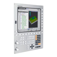
HEIDENHAIN TNC 320 User Manual (581 pages)
CNC control Conversational Programming
Brand:
HEIDENHAIN
| Category:
Control Systems
| Size: 15 MB
Table of Contents
Table of Contents
17
TNC 320 | User's Manual HEIDENHAIN Conversational Programming | 3/2014
37
First Steps with the TNC 320
43
Acknowledging the Power Interruption and Moving to the Reference Points
44
Machine Switch-On
44
Overview
44
Programming the First Part
45
Selecting the Correct Operating Mode
45
The most Important TNC Keys
45
Creating a New Program/File Management
46
Defining a Workpiece Blank
47
Program Layout
48
Programming a Simple Contour
49
Creating a Cycle Program
52
Graphically Testing the First Part
54
Selecting the Correct Operating Mode
54
Selecting the Tool Table for the Test Run
54
Choosing the Program You Want to Test
55
Selecting the Screen Layout and the View
55
Starting the Test Run
56
Preparing and Measuring Tools
57
Selecting the Correct Operating Mode
57
Setting up Tools
57
The Tool Table TOOL.T
58
The Pocket Table TOOL_P .TCH
59
Clamping the Workpiece
60
Selecting the Correct Operating Mode
60
Workpiece Setup
60
Datum Setting with 3-D Touch Probe
61
Choosing the Program You Want to Run
62
Running the First Program
62
Selecting the Correct Operating Mode
62
Start the Program
62
Introduction
63
Compatibility
64
Programming: HEIDENHAIN Conversational and ISO Formats
64
The TNC 320
64
Display Screen
65
Visual Display Unit and Operating Panel
65
Control Panel
66
Setting the Screen Layout
66
Manual Operation and El. Handwheel
67
Modes of Operation
67
Positioning with Manual Data Input
67
Programming
67
Program Run, Full Sequence and Program Run, Single Block
68
Test Run
68
General" Status Display
69
Status Displays
69
Additional Status Displays
70
Window Manager
76
Task Bar
77
Selinux Security Software
78
3-D Touch Probes
79
Accessories: HEIDENHAIN 3-D Touch Probes and Electronic Handwheels
79
HR Electronic Handwheels
80
Programming: Fundamentals, File Management
81
Fundamentals
82
Position Encoders and Reference Marks
82
Reference System
82
Designation of the Axes on Milling Machines
83
Reference System on Milling Machines
83
Polar Coordinates
84
Absolute and Incremental Workpiece Positions
85
Selecting the Datum
86
Opening Programs and Entering
87
Organization of an NC Program in HEIDENHAIN Conversational Format
87
Define the Blank: BLK FORM
88
Opening a New Part Program
90
Programming Tool Movements in Conversational
91
Actual Position Capture
93
Editing a Program
94
The TNC Search Function
97
File Manager: Fundamentals
99
Files
99
Data Backup
101
Displaying Externally Generated Files on the TNC
101
Directories
102
Paths
102
Working with the File Manager
102
Overview: Functions of the File Manager
103
Calling the File Manager
104
Selecting Drives, Directories and Files
105
Copying a Single File
106
Creating a New Directory
106
Creating a New File
106
Copying Files into Another Directory
107
Copying a Directory
108
Copying a Table
108
Choosing One of the Last Files Selected
109
Deleting a Directory
110
Deleting a File
110
Tagging Files
111
Renaming a File
112
Sorting Files
112
Additional Functions
113
Additional Tools for Management of External File Types
114
Data Transfer To/From an External Data Medium
119
The TNC in a Network
121
USB Devices on the TNC
122
Programming: Programming Aids
125
Screen Keyboard
126
Adding Comments
127
Functions for Editing of the Comment
128
Display of NC Programs
129
Structuring Programs
130
Calculator
131
Cutting Data Calculator
134
Programming Graphics
136
Block Number Display ON/OFF
137
Magnification or Reduction of Details
138
Error Messages
139
Detailed Error Messages
140
Clearing Errors
141
Keystroke Log
142
Informational Texts
143
Calling the Tncguide Help System
144
Tncguide Context-Sensitive Help System
145
Working with the Tncguide
146
Downloading Current Help Files
150
Programming: Tools
153
Entering Tool-Related Data
154
Spindle Speed S
155
Tool Data
156
Delta Values for Lengths and Radii
157
Enter Tool Data into the Table
158
Importing Tool Tables
166
Pocket Table for Tool Changer
167
Call Tool Data
170
Tool Change
172
Tool Usage Test
174
Tool Compensation
176
Tool Radius Compensation
177
Programming: Programming Contours
181
Tool Movements
182
Subprograms and Program Section Repeats
183
Fundamentals of Path Functions
184
Approaching and Departing a Contour
188
Important Positions for Approach and Departure
189
Approaching on a Straight Line with Tangential Connection: APPR LT
191
Approaching on a Circular Path with Tangential Connection: APPR CT
192
Approaching on a Circular Path with Tangential Connection from a Straight Line to the Contour APPR LCT
193
Departing in a Straight Line Perpendicular to the Last Contour Point: DEP LN
194
Departing on a Circular Path with Tangential Connection: DEP CT
195
Path Contours - Cartesian Coordinates
196
Straight Line L
197
Inserting a Chamfer between Two Straight Lines
198
Corner Rounding RND
199
Circle Center CC
200
Circular Path C Around Circle Center CC
201
Circlecr with Defined Radius
202
Circle CT with Tangential Connection
204
Example: Linear Movements and Chamfers with Cartesian Coordinates
205
Example: Circular Movements with Cartesian Coordinates
206
Example: Full Circle with Cartesian Coordinates
207
Path Contours – Polar Coordinates
208
Zero Point for Polar Coordinates: Pole CC
209
Circular Path CP Around Pole CC
210
Helix
211
Example: Linear Movement with Polar Coordinates
213
Example: Helix
214
Path Contours – FK Free Contour Programming
215
FK Programming Graphics
217
Initiating the FK Dialog
219
Free Straight Line Programming
220
Free Circular Path Programming
221
Input Options
222
Auxiliary Points
225
Relative Data
226
Example: FK Programming 1
228
Example: FK Programming 2
229
Example: FK Programming 3
230
Programming: Data Transfer from DXF Files or Plain-Language Contours
233
Processing DXF Files (Software Option)
234
Opening a DXF File
235
Basic Settings
236
Setting Layers
238
Defining the Datum
239
Selecting and Saving a Contour
241
Selecting and Saving Machining Positions
245
Programming: Subprograms and Program Section Repeats
251
Labeling Subprograms and Program Section Repeats
252
Subprograms
253
Calling a Subprogram
254
Program-Section Repeats
255
Calling a Program Section Repeat
256
Any Desired Program as Subprogram
257
Calling any Program as a Subprogram
258
Nesting
259
Subprogram Within a Subprogram
260
Repeating Program Section Repeats
261
Repeating a Subprogram
262
Programming Examples
263
Example: Groups of Holes
264
Example: Group of Holes with Several Tools
265
Programming: Q Parameters
267
Principle and Overview of Functions
268
Programming Notes
269
Calling Q Parameter Functions
270
Part Families—Q Parameters in Place of Numerical Values
271
Describing Contours with Mathematical Functions
272
Programming Fundamental Operations
273
Angle Functions (Trigonometry)
274
Calculation of Circles
275
If-Then Decisions with Q Parameters
276
Abbreviations Used
277
Checking and Changing Q Parameters
278
Additional Functions
280
FN 14: ERROR: Displaying Error Messages
281
FN 16: F-PRINT: Output of Formatted Texts and Q Parameter Values
285
FN 18: SYS-DATUM READ: Reading System Data
289
FN 19: PLC: Transfer Values to PLC
298
FN 29: PLC: Transfer Values to the PLC
300
Accessing Tables with SQL Commands
301
A Transaction
302
Programming SQL Commands
304
Sql Bind
305
Sql Select
306
Sql Fetch
308
Sql Update
309
Sql Commit
310
Entering Formulas Directly
311
Rules for Formulas
313
Programming Example
314
String Parameters
315
Assigning String Parameters
316
Converting a Numerical Value to a String Parameter
317
Copying a Substring from a String Parameter
318
Converting a String Parameter to a Numerical Value
319
Checking a String Parameter
320
Finding the Length of a String Parameter
321
Comparing Alphabetic Sequence
322
Reading Machine Parameters
323
Preassigned Q Parameters
326
Spindle Status: Q110
327
Coordinates after Probing During Program Run
328
Measurement Results from Touch Probe Cycles (See also User's Manual for Cycle Programming)
329
Programming Examples
331
Example: Concave Cylinder Machined with Spherical Cutter
333
Example: Convex Sphere Machined with End Mill
335
Programming: Miscellaneous Functions
337
Entering Miscellaneous Functions M and STOP
338
M Functions for Program Run Inspection, Spindle and Coolant
339
Miscellaneous Functions for Coordinate Data
340
Moving to Positions in a Non-Tilted Coordinate System with a Tilted Working Plane: M130
342
Miscellaneous Functions for Path Behavior
343
Machining Open Contour Corners: M98
344
Feed Rate Factor for Plunging Movements: M103
345
Feed Rate in Millimeters Per Spindle Revolution: M136
346
Feed Rate for Circular Arcs: M109/M110/M111
347
Calculating the Radius-Compensated Path in Advance (LOOK AHEAD): M120
348
Superimposing Handwheel Positioning During Program Run: M118
350
Retraction from the Contour in the Tool-Axis Direction: M140
352
Suppressing Touch Probe Monitoring: M141
353
Deleting Basic Rotation: M143
354
Automatically Retract Tool from the Contour at an NC Stop: M148
355
Rounding Corners: M197
356
Programming: Special Functions
357
Overview of Special Functions
358
Program Defaults Menu
359
Menu of Various Conversational Functions
360
Working with the Parallel Axes U, V and W
361
Function Paraxcomp Display
362
Function Paraxcomp off
363
Function Paraxmode off
364
File Functions
365
Definition of a Datum Shift
366
Trans Datum Table
367
Trans Datum Reset
368
Creating Text Files
369
Editing Texts
370
Editing Text Blocks
371
Finding Text Sections
372
Freely Definable Tables
373
Editing the Table Format
374
Switching between Table and Form View
375
FN 26: TAPOPEN: Open a Freely Definable Table
376
FN 27: TAPWRITE: Write to a Freely Definable Table
377
FN 28: TAPREAD: Read from a Freely Definable Table
378
Programming: Multiple Axis Machining
379
Functions for Multiple Axis Machining
380
Introduction
381
Defining the PLANE Function
383
Resetting the PLANE Function
384
Defining the Working Plane with the Spatial Angle: PLANE SPATIAL
385
Defining the Working Plane with the Projection Angle: PLANE PROJECTED
387
Defining the Working Plane with the Euler Angle: PLANE EULER
388
Defining the Working Plane with Two Vectors: PLANE VECTOR
390
Defining the Working Plane Via Three Points: PLANE POINTS
392
Defining the Working Plane Via a Single Incremental Spatial Angle: PLANE SPATIAL
394
Tilting the Working Plane through Axis Angle: PLANE AXIAL (FCL 3 Function)
395
Specifying the Positioning Behavior of the PLANE Function
397
Miscellaneous Functions for Rotary Axes
402
Shortest-Path Traverse of Rotary Axes: M126
403
Reducing Display of a Rotary Axis to a Value Less than 360°: M94
404
Selecting Tilting Axes: M138
405
Manual Operation and Setup
407
Switch-On, Switch-Off
408
Switch-Off
410
Moving the Machine Axes
411
Traverse with Electronic Handwheels
412
Spindle Speed S, Feed Rate F and Miscellaneous Function M
422
Adjusting Spindle Speed and Feed Rate
423
Datum Setting Without a 3-D Touch Probe
424
Datum Management with the Preset Table
425
Using 3-D Touch Probes
431
Functions in Touch Probe Cycles
432
Selecting Touch Probe Cycles
434
Recording Measured Values from the Touch-Probe Cycles
435
Writing Measured Values from the Touch Probe Cycles in a Datum Table
436
Writing Measured Values from the Touch Probe Cycles in the Preset Table
437
Calibrating a 3-D Touch Trigger Probe
438
Calibrating the Effective Length
439
Calibrating the Effective Radius and Compensating Center Misalignment
440
Displaying Calibration Values
442
Compensating Workpiece Misalignment with 3-D Touch Probe
443
Identifying Basic Rotation
444
Displaying a Basic Rotation
445
Datum Setting with 3-D Touch Probe
446
Corner as Datum
447
Circle Center as Datum
449
Setting a Center Line as Datum
451
Measuring Workpieces with a 3-D Touch Probe
452
Using Touch Probe Functions with Mechanical Probes or Measuring Dials
455
Application, Function
456
Traversing Reference Points in Tilted Axes
458
To Activate Manual Tilting
459
Setting the Current Tool-Axis Direction as the Active Machining Direction
460
Setting the Datum in a Tilted Coordinate System
461
Positioning with Manual Data Input
463
Programming and Executing Simple Machining Operations
464
Protecting and Erasing Programs in $MDI
467
Test Run and Program Run
469
Graphics
470
Speed of the Setting Test Runs
471
Overview: Display Modes
472
Plan View
473
D View
474
Repeating Graphic Simulation
477
Measurement of Machining Time
478
Showing the Workpiece Blank in the Working Space
479
Functions for Program Display
480
Test Run
481
Program Run
483
Running a Part Program
484
Interrupt Machining
485
Moving the Machine Axes During an Interruption
486
Retraction after a Power Interruption
488
Any Entry into Program (MID-Program Startup)
491
Returning to the Contour
493
Automatic Program Start
494
Optional Block Skip
495
MOD Functions
497
Tables and Overviews
525
Advertisement
HEIDENHAIN TNC 320 User Manual (724 pages)
ISO programming
Brand:
HEIDENHAIN
| Category:
Control Systems
| Size: 15 MB
HEIDENHAIN TNC 320 Operating Instructions Manual (64 pages)
Programming Station
Brand:
HEIDENHAIN
| Category:
Controller
| Size: 3 MB
Table of Contents
Table of Contents
7
1 Important Information on the Software for the Programming Station
9
1.1 Introduction
10
General Information
10
Options/Feature Content Level (FCL)
10
1.2 Compatibility
11
Downward Compatibility
12
Differences in Fixed Cycles
13
Differences in Touch Probe Cycles
19
Differences in Miscellaneous Functions M
27
Differences in Q-Parameter Programming
31
Differences in Other Functions
33
Working with the Programming Station
36
Starting the Programming Station
36
Showing the Virtual Keyboard
37
Exiting the Programming Station
37
Data Transfer from the Programming Station to the Machine Tool
39
Prerequisites
39
Preparations at the Programming Station
39
Calling a Program from the Machine Tool
40
Connection between the Programming Station and HEIDENHAIN PC Software
40
Special Features of the Demo Version
41
General Information
41
Starting the Demo Version
41
Keyboard Assignment
42
Overview of Keyboard Assignment
46
Key Assignment on Portable Computers
47
2 Items Supplied / Installation
49
Items Supplied / System Requirements
50
Items Supplied
50
System Requirements
51
Connecting the Programming Station
52
Connecting the Keyboard for the Programming Station
52
Mounting the Cable Clamps for the USB Cable
52
Number Stickers
53
Connecting the USB Dongle (for the Version with a Virtual Keyboard)
53
Connecting the USB Network Dongle (Only for the Version with a Virtual Keyboard)
53
Installing the Programming Station Software
54
Configuring the Programming Station Software for Use with a USB Network Dongle
55
Network License for Multiple Workstations
56
Setting the Conversational Language
58
Working with the HEIDENHAIN Basic PLC Program
60
Working with a Machine-Specific PLC Program
61
Displaying Additional Drives
61
Advertisement
Advertisement
Related Products
HEIDENHAIN TNC 370 D
HEIDENHAIN TNC155B
HEIDENHAIN TNC155Q
HEIDENHAIN TNC151Q
HEIDENHAIN TNC 150 B
HEIDENHAIN TNC 415 F
HEIDENHAIN TNC 425 E
HEIDENHAIN TNC 426 PA
HEIDENHAIN TNC 430 CE
HEIDENHAIN TNC7
HEIDENHAIN Categories
Media Converter
Measuring Instruments
Industrial Equipment
Control Systems
Control Unit
More HEIDENHAIN Manuals
Login
Sign In
OR
Sign in with Facebook
Sign in with Google
Upload manual
Upload from disk
Upload from URL