Sign In
Upload
Manuals
Brands
Heart Interface Manuals
Control Panel
LINK 1000
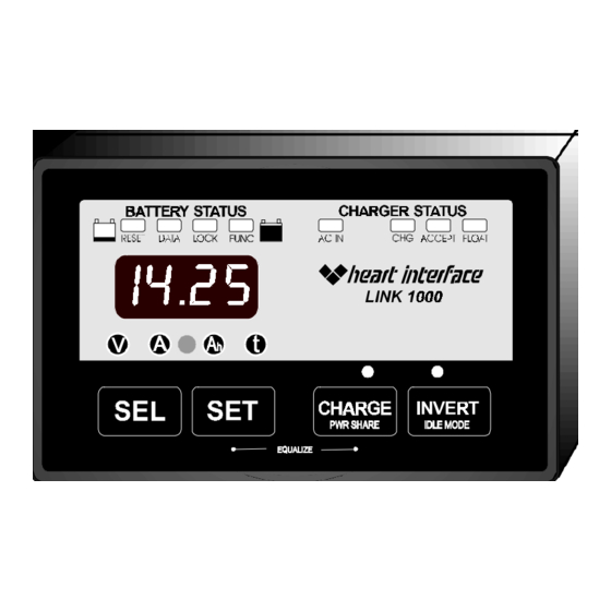
User Manuals: Heart Interface LINK 1000 Control Panel
Manuals and User Guides for Heart Interface LINK 1000 Control Panel. We have
1
Heart Interface LINK 1000 Control Panel manual available for free PDF download: Owner's Manual
Heart Interface LINK 1000 Owner's Manual (45 pages)
Brand:
Heart Interface
| Category:
Control Panel
| Size: 0 MB
Table of Contents
Applications
1
Operation
1
Installation
1
Table of Contents
2
Specifications
2
Introduction
3
Power Connection Warnings
3
Important Battery Facts
3
Using Your Link 1000
4
Display Lights
4
Reading the Light Bar
5
Inverter Functions
6
Marine and RV Operating Tip
6
Charge PWR Share
6
Invert Idle Mode
6
Idle Mode and Power Sharing
7
PWR Share
7
To Set or Change Pwr Share
7
To Set or Change Idle Mode
7
How to Use Your Link 1000
8
Simple Battery Management Rule
8
Overcharge Amp-Hours
8
Battery Capacity Testing
9
Capacity at Various Discharge Rates
9
Using Your Freedom to Test Battery Capacity
9
The Ideal Charge Curve
10
Ideal Charge Curve
10
Ideal Charge State Table
10
Factory Default Values
10
Synchronizing to Your Battery
11
Equalizing
12
Caution
12
Equalizing Gel Batteries
12
Setup Procedures
13
Inverter/Charge Controls
13
Monitoring Functions
13
Using Set and Sel Buttons
14
When to Set up V and a
15
Conditions to Reset Amp-Hours to Zero
15
Battery Chemistry Other than Lead Acid
15
Charged Voltage
16
Charged Current
16
Battery Capacity
17
How to Set
18
How to Set up Functions
19
Functions Table
19
F01 - Auto Display Scanning
19
F02 - Display Sleep
20
F03 - Set or Display Ambient Battery Temperature
20
If F16 Is On, F03 Displays Present Battery Temp
20
If F16 Is Off, F03 Displays Declared Battery Temp
20
Temperature Compensation Table
21
F04 - Toggle Display between a Hr and Kwhr
21
F05 - Alternative Energy Mode
21
F06 - Manually Set Cef
22
F07 - Set Temperature Coefficient
22
F08 - Set Peukert's Exponent
22
F09 - Low Battery Discharge Floor
22
F10 - Battery Type
23
F11 - Second Battery Voltage Sense
23
F13 - Number of Inverter Low Battery Shutdowns
23
F14 - Display Test
23
F16 - Active Temperature Compensation On, off
24
How to Reset Your Unit
25
To Access the Reset Functions
25
Data: Your Battery History
26
To Access the Data Displays
26
What the Historical Information Means
26
Cef
26
Lock
27
Kid Proofing
27
To Access the Lock
27
Setting Peukert Exponent
28
High Discharge Rates & Peukert's Equation
29
Typical Peukert's Exponents
31
Typical Values for Peukert's Exponent "N"
31
Prevailer & Seagel Batteries
31
Trojan Batteries
31
Surrette and Rolls Batteries
32
Calculating Peukert's Exponent
32
Error Codes
33
Inverter High DC/Battery Voltage Shutdown
33
Inverter Low DC/Battery Voltage Shutdown
33
Inverter or Charger over Temp Shutdown
33
To Verify Current Measurements
34
Depowered
34
Spare
34
Battery #1 Voltage Sense Leads Open
34
Set up & Historical Data
35
General Notes
37
Wire by Wire Detail
39
Battery Compartment
39
Wiring Connections to the Link 1000
40
Top Rear View
40
Wire by Wire Check
41
DC Power (Black Wire)
41
Shunt Sense Lead Load Side (Green Wire)
41
Battery Side of Shunt (Orange Wire)
41
Mounting
42
Looking at Nesting Plate as It Mounts on Wall
42
Removing the Unit
43
Startup
44
Factory Default Settings
44
Advertisement
Advertisement
Related Products
Heart Interface LINK 20
Heart Interface LINK 2000
Heart Interface Categories
Battery Charger
Control Unit
Monitor
Microphone
Inverter
More Heart Interface Manuals
Login
Sign In
OR
Sign in with Facebook
Sign in with Google
Upload manual
Upload from disk
Upload from URL