Table of Contents
Advertisement
02/11/98
Manual Part # 890030
This manual applies to Link 1000 with serial number above 1900.
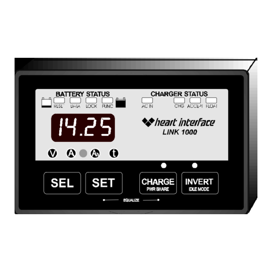
The Link 1000 is an instrumentation and control panel
designed for use with Heart Interface Freedom series inverter/chargers
operated with a single battery bank. For installations with a Freedom
inverter/charger and two battery banks, the Link 2000 is recommended.
For instrumentation of a single battery bank (no inverter control) the Link 10
is recommended, while the Link 20 is recommended for instrumention of a
two battery bank system (no inverter control).
Instructions how to operate your Link 1000 begin on page 4
of this manual.
This manual contains easy to follow installation instructions
beginning on Page 37.
Warranty issues should be directed to Heart Interface.
Please do not route warranty issues through your dealer. See Page 36.
th
21440 68
Ave. So. Kent, WA 98032
1
(253) 872-7225 Toll Free 1-800-446-6180
Link1000Revc.pm6
Advertisement
Table of Contents

Summary of Contents for Heart Interface LINK 1000
- Page 1 02/11/98 Manual Part # 890030 This manual applies to Link 1000 with serial number above 1900. The Link 1000 is an instrumentation and control panel designed for use with Heart Interface Freedom series inverter/chargers operated with a single battery bank. For installations with a Freedom inverter/charger and two battery banks, the Link 2000 is recommended.
- Page 2 Required Reading Prior to Installation Page 37-38 Wiring Connections Page 39-40 Wire By Wire Check Page 41 Mounting the Link 1000 Page 42-43 Start Up Procedure Page 44 LINK 1000 Power Supply Voltage 8-40 Volts DC (Not for use with 32V Systems)
- Page 3 Please contact us with suggested improvements. For Link 1000 installation and operation questions please call Heart Interface. For warranty support and repair please call Cruising Equipment. This symbol is used to point out very important sections of this manual or to indicate items that may need to be changed through Set Up routines.
- Page 4 (unsigned) number. Amp-hours (A hrs) consumed represents the amount of en- ergy removed from the battery. If you run a 10 Amp load for one hour, 10 Amp-hours are consumed. Your Link 1000 display. During charging the Link will show...
- Page 5 Four lights green means a nearly full battery. A single flashing red light means it's nearly discharged. The light bar scaling is adjustable. As your Link 1000 comes from the factory, it is set to show a flashing red light whenever your bat- tery is more than 80% discharged (20% charged).
- Page 6 02/11/98 The Link 1000 communicates with the Freedom inverter/charger via a telephone cable. When the CHARGE button is pressed, the Link 1000 sends a "charger on" command to the Freedom inverter/charger. The green light above the button is lit when the "charger on" command is sent.
- Page 7 02/11/98 PWR SHARE: Power Share automatically reduces the Freedom 's charger out- put if the AC load through the automatic transfer switch exceeds a settable current limit. This load management feature helps prevent external source AC supply breakers from tripping when the charger, water heater, and perhaps other loads, all come on at once. The default value is 30Amps (or OFF for Freedom 25).
- Page 8 The Link 1000 is a guide to the battery's state of charge. Our Mid-Capacity Rule says you should begin charging when your Link 1000 shows that 50% (or more) of battery capacity has been consumed. In Marine and RV systems, which are trying to minimize charging time with an engine driven alternator, or generator powered charging, the battery is normally charged only to the 85% level.
- Page 9 10.5 volts (or 21 volts if you're testing a 24V system), hopefully about 20 hours later, turn off the load and look at the A hrs display on your Link 1000 . The A hrs displayed is your actual battery capacity.
- Page 10 02/11/98 The Link 1000 transmits critical battery state of charge information to the Freedom inverter/charger. This enables the charger to conform to our proven Ideal Charge Curve with four basic cycles; CHARGE, ACCEPTANCE, FLOAT, and EQUALIZE. The CHARGE cycle supplies full charger output current until the battery reaches the Acceptance charging voltage (14.4V typ.).
- Page 11 There are two ways to synchronize your Link 1000 : 1) Install the Link 1000 on a fully charged battery and it will be in sync. 2) If the Link 1000 is installed on a partially charged battery, simply charge with your Freedom inverter/charger until the charged parameters are met.
- Page 12 To terminate EQUALIZE early on Freedom s prior to serial #100,000, you must turn off both the CHARGE and INVERT buttons on the Link 1000 . Equalizing causes your battery to gas. You should check your battery electrolyte ("water") level before and after Equalizing.
- Page 13 02/11/98 Your Link 1000 comes with default values chosen to work with most systems. Normally the only values that may need to be changed are: The battery capacity, battery type (liquid or gelled), temperature, and high discharge rate com- pensation (Peukert) exponent. Please be sure you understand each function before changing the factory default values.
- Page 14 02/11/98 Press and hold the SET button until SEL is displayed to access the Set Up and Advanced Functions modes. With SEL displayed, press the SEL button to choose the function you want to SELect. Pressing SEL chooses a variable or function. The Set Up mode always begins at the Each press of the SEL button scrolls to the next item.
- Page 15 02/11/98 The Link 1000 depends on correctly set Charged Parameters to stay in sync with battery state-of-charge, to automatically reset to zero, and to automatically calculate the Charging Efficiency Factor (CEF) of your battery. The two numbers which define Charged Parameters are: Charged Voltage and Charged Current Percent.
- Page 16 The Link 1000 is factory set to use 2% of battery capacity as its Charging Current Percentage. If you normally end charging before 2% is reached, or use a very large battery bank, such as might be encountered in an alternative energy installation, a different value may be appropriate.
- Page 17 02/11/98 The first time you apply power to a Link 1000 , it assumes you have 200 Amp- hours of battery capacity. 200 Amp-hours is the factory default capacity. If your battery capacity is different (and it probably is) you must change the declared battery capacity.
- Page 18 02/11/98 There are four different ways the Link 1000 can calculate the time of operation remaining. You may select present consumption level, a four minute rolling average, a sixteen minute, or a 32 minute rolling average. Which method is best for you depends on your installation.
- Page 19 02/11/98 When the FUNC light is on, you can access Advanced Functions of the Link 1000 . The values for each function are changed using the SET and SEL keys. 1) Hold down the SET button until the numeric display says 2) Now press the SEL button 11 times until appears in the display.
- Page 20 IF F16 IS ON, F03 DISPLAYS PRESENT BATTERY TEMP. ( This function is only available if your Freedom inverter/charger is equipped with a Heart Interface TC2+2 temperature sensing unit. Turn off scanning (F01) to see the reported temperature continously. After time out, the time indicator light will blink during this continous display .
- Page 21 When this function is selected the A hr display is changed to a kilowatt-hour display. Kilowatt-hours are used by your Link 1000 to determine if 100% of the energy consumed from the battery has been returned. A recalculation of the CEF is not permitted unless this counter is greater than 0.00 kWhr.
- Page 22 RANGE: 50% - 100% STEP: 5% Your Link 1000 allows you to declare the discharge floor used for meter calculations. As supplied by the factory, the discharge floor is 100% of Amp-hour capacity, cor- rected for high discharge rates. If you set the discharge floor to 100%, the TIME remaining display essentially reports TIME to "dead battery".
- Page 23 Heart Interface to keep track of which version of software is installed in your Link 1000 . This number should be written down in the Set Up table contained in this manual on Page 35 for your future reference.
- Page 24 DEFAULT: OFF RANGE: OFF, ON When this function is turned on, the Link 1000 utilizes the actual battery tem- perature reported to the Freedom inverter/charger by a Heart TC2+2 unit. It is recommended that this function not be turned ON if the Heart Inverter with...
- Page 25 02/11/98 RESET: Two types of RESET are provided: Resetting of Amp-hours to zero or a complete reset of all parameters to factory default settings. RESET Hold down the SET button until SEL appears in the numeric display.. Press the SEL button five times until the red light above the word RESET appears. AH is shown in the numeric display.
- Page 26 02/11/98 DATA: The DATA mode is used to recall key historical information about the battery. DATA Hold down the SET button until SEL appears in the numeric display.. Press the SEL button six times until the red light above the word DATA appears. The first number displayed will be Charging Efficiency Factor.
- Page 27 02/11/98 LOCK: The LOCK mode is used to keep kids (or others) from changing your Link 1000 Set Up. LOCK Hold down the SET button until SEL appears in the numeric display. Press the SEL button 10 times until the red light above the word LOCK appears.
- Page 28 1.00 and continue incrementing up. After 10 seconds, if no keys are pressed, the Link 1000 exits the Set Up mode and the selected value is stored as the new Peukert's exponent and the display returns to...
- Page 29 ) , that bracket your normal range of operation, allows you to calculate an "n" which will describe this varying effect. The Link 1000 uses a default value of "n" equal to 1.25 which is typical for many liquid cell batteries. Setting Battery Type 1, 2, (gel cell) or 3 (AGM) changes the Peukert exponent to 1.11, a common exponent for...
- Page 30 02/11/98...
- Page 31 02/11/98 Typical Values for Peukert's Exponent "n" This table contains values for the exponent "n" for various batteries and manufacturers. They are calculated from the 20 hour rating and the Reserve Minutes @ 25A as supplied by the manufacturer. They should be considered only a guide for selecting "n".
- Page 32 02/11/98 Surrette and Rolls Batteries Model Volts Res. Min. 20 Hr. Rating "n" EHG-208 1.42 EIG-225 1.54* EIG-262 1.72* 24/90 1.16 27/12M 1.23 30H/108 1.08 HT/4D 1.15 HT/8D 1.20 *Use Max allowed "n" of 1.50 CALCULATING PEUKERT'S EXPONENT Example of using Reserve Minutes @ 25 Amps and the 20 hour rate to calculate "n".
- Page 33 02/11/98 The following error codes are displayed when the Link 1000 detects a problem. The display alternates between the selected monitoring function and the Error Code. The Error Code continues to flash until the error is corrected. Error codes are the same for all models.
- Page 34 Displayed on first power up and whenever power has been interrupted or dipped below the operating voltage of the Link 1000 . This can be caused by voltage dips during engine starting if the meter is powered by the same battery that starts the engine.
- Page 35 Ahrs displayed ______________ ALT. ENERGY (F05) ______________ Manual CEF (F06) 95% (This value should only be set if you do NOT want your Link 1000 to automatically calculate CEF) ______________ TEMP. COEF. (F07) ______________ PEUKERT EXP. (F08) 1.25 ______________ DISCH. FLOOR...
- Page 36 LINK products are a joint venture of two Valley Forge Companies. Installation and operation questions should be directed to Heart Interface. Warranty issues should be directed to Cruising Equipment Co.. DO NOT INSTALL OR ATTEMPT TO USE THIS PRODUCT UNTIL YOU HAVE READ THE OWNER’S MANUAL IN ITS ENTIRETY.
- Page 37 All wiring should be done before installing the meter power fuse. GENERAL NOTES 1) Wiring to the Link 1000 should be #16 or #18 AWG. (Larger is OK, but not necessary.) Wiring should be in accordance with the NEC, ABYC, or other applicable standards.
- Page 38 0.5V. In most instances, a better solution is to use a battery combiner which keeps a starting battery charged without a voltage drop. 8) Second (Starting) Battery Voltage Sensing is an option on your Link 1000 . As supplied from the factory, the optional voltage sense circuit is Off. If you connect the positive terminal (+) of your starting battery to Pin #6 of the meter (through a 2 Amp fuse!), you can read the voltage of the starting battery.
- Page 39 1 2 3 4 5 6 7 8 9 0 1 2 3 4 5 6 7 8 9 0 1 2 3 4 5 6 7 8 9 0 1 2 1 2 battery Voltage Sense via 2 Amp Fuse Cable to Link 1000...
- Page 40 02/11/98 Link 1000 Make the necessary wire connections to the Link 1000 as shown in the following diagram: CAUTION Use correct sized screwdriver for terminal BACK OF screws. Tighten firmly but do not over-tighten UNIT to avoid damage. NOTE: The screw terminal is a small part.
- Page 41 (Color code shown is for Heart Interface cable) - DC Power (Black Wire). Start at terminal #1 of the Link 1000 and follow it to the big bolt on the Load side of the shunt. Do not connect this wire to the small screw terminal with the Green shunt sense lead.
- Page 42 02/11/98 Surface mounting (Recommended method) . Your Link 1000 is supplied with a nesting type mounting place which allows suface mounting using our exclusive Thin-Mount technology. Looking at nesting plate as it mounts on wall Pan head screws go here...
- Page 43 02/11/98 Demounting the Link 1000 from the nesting recepticle is a simple matter of inserting a small coin, knife blade, or small screwdriver blade and pressing inward while gently pulling the meter way from the nest. Press in on this tab with a thin metal coin while pulling one side of the unit away from the nesting recepticle.
- Page 44 A "ragged" power up may cause a meter lock up. Both the light bar and digital display should come on. Next, plug in the phone cable that allows the LINK 1000 to "talk" to the Free- dom inverter/charger. Note that the AC status light should now come on if there's AC power to the Freedom.
Need help?
Do you have a question about the LINK 1000 and is the answer not in the manual?
Questions and answers
I have a E 12 code Checked blue wire have power . Help
The E12 code for the Heart Interface LINK 1000 indicates that the Battery #1 voltage sense leads are open. To troubleshoot this issue, check the fuse or any other connections in the voltage sense lead (Blue wire) to Battery #1. Ensure all connections are secure and that the fuse is intact.
This answer is automatically generated
@Mr. Anderson i got 12volts to blue wire