Sign In
Upload
Manuals
Brands
HART Manuals
Measuring Instruments
Proline Promag H 300
HART Proline Promag H 300 Manuals
Manuals and User Guides for HART Proline Promag H 300. We have
1
HART Proline Promag H 300 manual available for free PDF download: Operating Instructions Manual
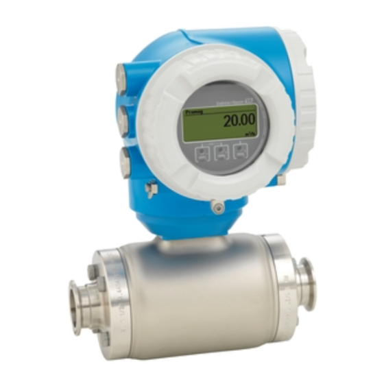
HART Proline Promag H 300 Operating Instructions Manual (184 pages)
Electromagnetic flowmeter
Brand:
HART
| Category:
Measuring Instruments
| Size: 8 MB
Table of Contents
Operating Instructions
1
Table of Contents
3
1 Document Information
6
Document Function
6
Symbols Used
6
Safety Symbols
6
Electrical Symbols
6
Communication Symbols
6
Tool Symbols
7
Symbols for Certain Types of Information
7
Symbols in Graphics
7
Documentation
8
Standard Documentation
8
Supplementary Device-Dependent Documentation
8
Registered Trademarks
9
2 Basic Safety Instructions
10
Requirements for Personnel
10
Designated Use
10
Workplace Safety
11
Operational Safety
11
Product Safety
11
IT Security
12
Device-Specific IT Security
12
Protecting Access Via Hardware Write Protection
12
Protecting Access Via a Password
12
Access Via Fieldbus
13
Access Via Web Server
13
3 Product Description
14
Product Design
14
4 Incoming Acceptance and Product
15
Identification
15
Incoming Acceptance
15
Product Identification
16
Transmitter Nameplate
17
Sensor Nameplate
18
Symbols on Measuring Device
19
5 Storage and Transport
20
Storage Conditions
20
Transporting the Product
20
Measuring Devices Without Lifting Lugs
20
Measuring Devices with Lifting Lugs
21
Transporting with a Fork Lift
21
Packaging Disposal
21
6 Installation
22
Installation Conditions
22
Mounting Position
22
Requirements from Environment and Process
24
Special Mounting Instructions
26
Mounting the Measuring Device
26
Required Tools
26
Preparing the Measuring Device
26
Mounting the Sensor
26
Turning the Transmitter Housing
29
Turning the Display Module
29
Post-Installation Check
30
7 Electrical Connection
31
Connection Conditions
31
Required Tools
31
Requirements for Connecting Cable
31
Terminal Assignment
33
Preparing the Measuring Device
33
Connecting the Measuring Device
33
Connecting the Transmitter
33
Connecting Remote Display and Operating Module DKX001
36
Ensure Potential Equalization
36
Requirements
36
Connection Example, Standard Scenario
36
Connection Example in Special Situations
36
Special Connection Instructions
38
Connection Examples
38
Ensuring the Degree of Protection
42
Post-Connection Check
42
8 Operation Options
43
Overview of Operation Options
43
Structure and Function of the Operating Menu
44
Structure of the Operating Menu
44
Operating Philosophy
45
Display
46
Operational Display
46
Navigation View
47
Editing View
49
Operating Elements
51
Opening the Context Menu
51
Navigating and Selecting from List
53
Calling the Parameter Directly
53
Calling up Help Text
54
Changing the Parameters
55
User Roles and Related Access Authorization
56
Disabling Write Protection Via Access
56
Code
56
Enabling and Disabling the Keypad
56
Access to the Operating Menu Via the Web Browser
57
Function Range
57
Prerequisites
57
Establishing a Connection
59
Logging on
60
User Interface
61
Disabling the Web Server
62
Logging out
62
Access to the Operating Menu Via the Operating Tool
62
Connecting the Operating Tool
63
Field Xpert SFX350, SFX370
65
Fieldcare
66
Devicecare
67
AMS Device Manager
67
Simatic Pdm
68
Field Communicator 475
68
9 System Integration
69
Overview of Device Description Files
69
Current Version Data for the Device
69
Operating Tools
69
Measured Variables Via HART Protocol
69
Other Settings
71
Burst Mode Functionality in Accordance with HART 7
71
Specification
71
10 Commissioning
74
Function Check
74
Switching on the Measuring Device
74
Setting the Operating Language
74
Configuring the Measuring Device
74
Defining the Tag Name
76
Setting the System Units
76
Displaying the I/O Configuration
78
Configuring the Status Input
78
Configuring the Current Input
79
Configuring the Current Output
80
Configuring the Pulse/Frequency
83
Switch Output
83
Configuring the Local Display
89
Configuring the Low Flow Cut off
91
10.4.10 Configuring Empty Pipe Detection
92
10.4.11 Configuring the HART Input
92
10.4.12 Configuring the Relay Output
94
10.4.13 Configuring the Double Pulse Output
96
Advanced Settings
98
Carrying out a Sensor Adjustment
99
Configuring the Totalizer
99
Carrying out Additional Display Configurations
101
Performing Electrode Cleaning
104
WLAN Configuration
105
Configuration Management
106
Using Parameters for Device Administration
107
Simulation
109
Protecting Settings from Unauthorized
112
Access
112
Write Protection Via Write Protection
113
Switch
113
11 Operation
115
Reading the Device Locking Status
115
Adjusting the Operating Language
115
Configuring the Display
115
Reading Measured Values
115
Process Variables
115
Totalizer" Submenu
117
Input Values" Submenu
117
Output Values
118
Adapting the Measuring Device to the Process
121
Conditions
121
Performing a Totalizer Reset
121
Function Scope of the "Control Totalizer" Parameter
122
Function Scope of the "Reset All Totalizers" Parameter
122
Showing Data Logging
122
12 Diagnostics and Troubleshooting
125
General Troubleshooting
125
Diagnostic Information Via Light Emitting
127
Diodes
127
Transmitter
127
Diagnostic Information on Local Display
129
Diagnostic Message
129
Calling up Remedial Measures
131
Diagnostic Information in the Web Browser
131
Diagnostic Options
131
Calling up Remedy Information
132
Diagnostic Information in Devicecare or
133
Fieldcare
133
Diagnostic Options
133
Calling up Remedy Information
134
Adapting the Diagnostic Information
134
Adapting the Diagnostic Behavior
134
Adapting the Status Signal
134
Overview of Diagnostic Information
135
Pending Diagnostic Events
139
Diagnostic List
140
12.10 Event Logbook
140
12.10.1 Event History
140
12.10.2 Filtering the Event Logbook
141
12.10.3 Overview of Information Events
141
12.11 Resetting the Measuring Device
143
12.11.1 Function Scope of the "Device Reset" Parameter
143
12.12 Device Information
143
12.13 Firmware History
145
13 Maintenance
146
Maintenance Tasks
146
Exterior Cleaning
146
Interior Cleaning
146
Replacing Seals
146
Measuring and Test Equipment
146
Endress+Hauser Services
146
14 Repairs
147
General Notes
147
Repair and Conversion Concept
147
Notes for Repair and Conversion
147
Spare Parts
147
Endress+Hauser Services
147
Return
147
Disposal
148
Removing the Measuring Device
148
Disposing of the Measuring Device
148
15 Accessories
149
Device-Specific Accessories
149
For the Transmitter
149
For the Sensor
149
Communication-Specific Accessories
150
Service-Specific Accessories
150
System Components
151
16 Technical Data
152
Application
152
Function and System Design
152
Input
152
Output
155
Power Supply
160
Performance Characteristics
161
Installation
162
Environment
162
Process
163
16.10 Mechanical Construction
165
16.11 Operability
168
16.12 Certificates and Approvals
172
16.13 Application Packages
174
16.14 Accessories
174
16.15 Supplementary Documentation
175
Index
177
Advertisement
Advertisement
Related Products
HART HART475
Hart Proline Promag 400
HART Proline Promag 55
HART HTEDG
HART HTMS33
HART HPRC01B
HART HPCP01
HART HACJ02
HART HPDD02
HART HZRL50
HART Categories
Vacuum Cleaner
Power Tool
Drill
Saw
Measuring Instruments
More HART Manuals
Login
Sign In
OR
Sign in with Facebook
Sign in with Google
Upload manual
Upload from disk
Upload from URL