Sign In
Upload
Manuals
Brands
HarmonicDrive Manuals
Servo Drives
H A - 800A
User Manuals: HarmonicDrive H A - 800A Servo Drives
Manuals and User Guides for HarmonicDrive H A - 800A Servo Drives. We have
1
HarmonicDrive H A - 800A Servo Drives manual available for free PDF download: Manual
HarmonicDrive H A - 800A Manual (314 pages)
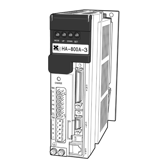
HA-800A series AC Servo Driver
Brand:
HarmonicDrive
| Category:
Servo Drives
| Size: 10 MB
Table of Contents
Safety Guide
3
Limitation of Applications
3
Safety Note
4
Structure of this Document
7
Table of Contents
8
Table of Contents
9
Related Manual
14
Related Actuator/Driver Standards
15
Compatible Standards
16
Conformance to European EC Directives
17
Chapter 1 Functions and Configuration
22
Overview of Drivers
22
Overview of Functions
22
Function Block Diagram
23
Device Configuration Diagram
24
Driver Model
26
Actuator and Extension Cable Combinations
27
Driver Ratings and Specifications
28
Function List
32
External Drawing
34
Name and Function of each Part of a Display Panel
36
Chapter 2 Installation/Wiring
40
Receiving Inspection
40
Check Procedure
40
Installation Location and Installation
41
Installation Environment
41
Notices on Installation
41
Installation Procedure
42
Connecting Power Cables
44
Allowable Cable Sizes
44
Connecting Power Cables
45
Protecting Power Lines
47
Connecting a Ground Wire
47
Power on and off Sequences
48
Suppressing Noise
53
Grounding
53
Installing Noise Filters
54
Wiring the Driver and Motor
56
Connecting the Motor
56
Connecting the Encoder
57
Wiring the Host Device
58
Connecting the Host Device
58
Connecting the Personal Computer (PSF-800)
59
Chapter 3 Startup
62
Startup Procedures
62
Startup Procedures
63
Turning on the Power for the First Time
64
Details on Control Power Supply on
65
Troubleshooting Upon Power on
69
Operation Check with the Actuator Alone
70
Troubleshooting at Operation Check
71
Operation Check with the Actual System
74
Troubleshooting at Actual Operation Check
75
Manual Gain Adjustment Method
76
Position Control
76
Speed Control
77
Applied Servo Gain Adjustment Function
79
Normal Operation
83
Notices for Normal Operations
83
Daily Maintenance/Inspection
83
Periodically Replaced Parts
84
Backup Battery
84
How to Replace the Backup Battery
85
Chapter 4 Encoder System
88
Overview of Encoders
88
17-Bit Absolute Encoder
91
Features
91
Startup
93
Origin Setting
95
Data Output
96
Remedial Actions for Errors/Warnings
100
13-Bit Absolute Encoder
102
Features
102
Startup
104
Origin Setting
105
Data Output
106
Remedial Actions for Errors/Warnings
110
Incremental Encoder
112
Startup
114
Remedial Action for Error
116
Chapter 5 I/O Signals
118
I/O Signal List
118
Pin Numbers and Names of I/O Signals
118
Models of I/O Signal Connector CN2
119
Input Signals: System Parameter SP00 to SP16
120
Input Signal Connection Circuit
121
Input Signal List
123
List of Parameter Set Values
124
Details of Input Signals
126
Inputs in each Control Mode
133
Position Command Mode
133
Speed Command Mode
137
Torque Command Mode
138
Output Signals: System Parameter SP20 to SP26
140
Output Signal Connection Circuit
141
Output Signal List
142
Details of Output Signals
143
Monitor Output
145
Encoder Output
145
Current Value Data Output
145
Analog Waveform Monitoring
146
Digital Signal Monitor
147
Connection Example in Control Mode
148
Connection Example with Default Settings
148
Connection Example in Position Control Mode
149
Connection Example in Speed Control Mode
150
Connection Example in Torque Control Mode
151
Chapter 6 Panel Display and Operation
153
Operating Display Panel
154
Overview of Modes
154
Initial Panel Display
155
Panel Display Hierarchy
156
Operation Outline of Status Display Mode
157
Operation Outline of Alarm Mode
158
Operation Outline of Tune Mode
159
Operation Outline of System Parameter Mode
161
Operation Outline of Test Mode
165
Chapter 7 Status Display Mode/Alarm Mode/Tune Mode
168
Status Display Mode
168
Status Display Mode List
168
Details of Status Display Mode
170
D01, 02: Error Pulse Count Display
170
D04: Overload Rate Display
171
D05, 06: Feedback Pulse Display
172
D07, 08: Command Pulse Display
172
D11: Speed Command Voltage
173
D12: Torque Command Voltage
173
D13: Applicable Actuator Code
174
D16: Regenerative Power (HA-800-24 Only)
175
Alarm Mode
176
Alarm Display
176
Alarm List
177
AL: Present Alarm/Warning Display
177
Ahclr: Alarm History Clear
178
Tune Mode
179
Details of Tune Mode
180
AJ00: Position Loop Gain
180
AJ01: Speed Loop Gain
180
AJ02: Speed Loop Integral Compensation
181
AJ03: Feed-Forward Gain
181
AJ04: In-Position Range
181
AJ05: Attained Speed Judgment Value
182
AJ06: Attained Torque Judgment Value
182
AJ07: Zero Speed Judgment Value
182
AJ08 to 10: Internal Speed Command 1 to 3
183
AJ11: Torque Limit
183
AJ12: Acceleration Time Constant
184
AJ13: Deceleration Time Constant
184
AJ14: External Speed Command Offset
185
AJ15: External Torque Command Offset
185
AJ16: Speed Monitor Offset
185
AJ17: Current Monitor Offset
185
AJ20: Feed-Forward Filter
186
AJ21: Load Inertia Moment Ratio
186
AJ22: Torque Constant Compensation Factor
186
AJ23: Spring Constant Compensation Factor
187
AJ24: Positioning Automatic Gain
187
Chapter 8 System Parameter Mode
189
System Parameter Mode
190
Function Extension Parameter
192
SP40: CN9-CP3 Output Signal Setting
193
SP41: Control Mode Switching Setting
193
SP42: Command Pulse Input Pattern Setting
194
SP43: Multiplication of 2-Phase Input Setting
194
SP44 to 47: Electronic Gear Setting
195
SP48: Deviation Clear Upon Servo-ON Setting
196
SP49: Allowable Position Deviation
196
SP50: Command Polarity
196
SP51: Speed Input Factor Setting
198
SP52: Zero Clamp
198
SP53: Torque Input Factor Setting
198
SP54: Status Display Setting
199
SP55: DB Enable/Disable Setting
199
SP56: External Speed Limit Enable/Disable
199
SP57: External Torque Limit Enable/Disable
199
SP59: Angle Compensation Enable/Disable Setting
200
SP60: Automatic Positioning Gain Setting Enable/Disable Setting
200
SP61: Encoder Monitor Output Pulses
200
SP64: Regenerative Resistor Selection (HA-800-24 Only)
201
SP65: FWD/REV Inhibit Operation
201
SP66: Absolute Encoder Function Setting
201
SP67: Output Shaft Divide Function Setting
202
SP69: Feed-Forward Control Function Setting
205
Chapter 9 Test Mode
207
Test Mode
207
Details of Test Mode
209
T00: I/O Signal Monitor
209
T01: Output Signal Operation
210
T02: JOG Speed Setting
211
T03: JOG Acceleration/Deceleration Time Constant Setting
212
T04: JOG Operation
213
T05: Parameter Initialization
214
T06: Automatic Adjustment of Speed Command Offset
215
T07: Automatic Adjustment of Torque Command Offset
216
T08: Multi Revolution Clear
217
T09: Auto-Tuning
218
T10: Auto-Tuning Displacement
220
T11: Auto-Tuning Level Selection
221
Chapter 10 Communication Software
224
Overview
224
Setup
224
Initial Screen
227
Status Display
230
Auto-Tuning
232
Parameter Setting
234
Assigning I/O Signals
236
Saving and Reading Set Values
239
Saving Set Parameter Values
239
Reading Saved Set Value Files
240
Comparing a Saved Settings File with Internal Set Values of the Driver
241
10-5-4. Writing a Saved Settings File to the Driver
243
Test Operation
245
Output Signal Operation
247
IO Monitor
248
Waveform Monitoring
249
Alarms
252
Chapter 11 Troubleshooting
253
Alarms and Remedial Actions
254
Remedial Action for Alarm
255
Warnings and Remedial Actions
267
Warning List
267
Remedial Action for Warning
268
Chapter 12 Option
271
Extension Cables
272
Option
272
Dedicated Communication Cable
273
Connectors
273
Servo Parameter Setting Software
274
Backup Battery
275
Monitor Cable
275
Appendix A-1 Default Settings
278
Regenerative Resistor
284
External Regenerative Resistor
285
Allowable Load Inertia
291
List of Data Retained in the Driver
297
Driver Replacement Procedures
300
Notices for Using SHA-CG(-S
302
Control Block Diagram
308
Position Control Mode
308
A-6 Control Block Diagram
308
Speed Control Mode
309
Torque Control Mode
309
Advertisement
Advertisement
Related Products
HarmonicDrive Categories
Controller
Servo Drives
More HarmonicDrive Manuals
Login
Sign In
OR
Sign in with Facebook
Sign in with Google
Upload manual
Upload from disk
Upload from URL