Table of Contents
Troubleshooting

Summary of Contents for HarmonicDrive H A - 800A
- Page 1 100V/200V power supply AC Servo Driver H A - 8 0 0 A s e r i e s m a n u a l (for SHA, FHA-Cmini, FHA-C, RSF/RKF series) ISO14001 (Hotaka plant) This operation manual covers the following software ISO9001 versions: ●Ver 3.x...
- Page 2 Introduction Thank you very much for your purchasing our HA-800A series servo driver. Wrong handling or use of this product may result in unexpected accidents or shorter life of the product. Read this document carefully and use the product correctly so that the product can be used safely for many years.
-
Page 3: Safety Guide
SAFETY GUIDE To use this driver safely and correctly, be sure to read SAFETY GUIDE and other parts of this document carefully and fully understand the information provided herein before using the driver. NOTATION Important safety information you must note is provided herein. Be sure to observe these instructions. Indicates a potentially hazardous situation, which, if not avoided, could result in death or serious personal injury. -
Page 4: Safety Note
SAFETY GUIDE SAFETY NOTE CAUTIONS FOR ACTUATORS AT APPLICATION DESIGNING Always use under followings conditions: The actuator is designed to be used indoors. Observe the following conditions: ・ Ambient temperature: 0℃ to 40℃ CAUTION ・ Ambient humidity: 20% to 80%RH (Non-condensation) ・... - Page 5 SAFETY GUIDE CAUTIONS FOR DRIVERS AT APPLICATION DESIGNING Always use drivers under followings conditions: ・ Mount in a vertical position keeping sufficient distance to other devices to let heat generated by the driver radiate freely. CAUTION ・ 0℃ to 50℃, 95% RH or below (Non condensation) ・...
- Page 6 SAFETY GUIDE Do not make a voltage resistance test. ・ Failure to observe this caution may result in damage of the control unit. ・ Please consult our sales office, if you intent to make a voltage CAUTION resistance test. Do not operate control units by means of power ON/OFF switching.
-
Page 7: Structure Of This Document
Structure of this document Overviews of driver models, specifications, external dimensions, Functions Chapter 1 configuration etc., are explained. Receiving inspection, environment, power wiring, noise suppression Chapter 2 Installation/wiring and connector wiring are explained. Startup procedures to be followed when the driver is used for the Chapter 3 Startup first time, from receiving inspection to operation of the actual... -
Page 8: Table Of Contents
Table of contents SAFETY GUIDE ...................... 1 NOTATION ....................... 1 LIMITATION OF APPLICATIONS ................1 SAFETY NOTE ......................2 Structure of this document ..................5 Table of contents ..................... 6 Related manual ..................... 12 Related actuator/driver standards ................. 13 Compatible standards .................... 14 Conformance to European EC Directives .............. -
Page 9: Table Of Contents
Table of contents Suppressing noise ................... 2-14 Grounding ......................2-14 Installing noise filters ................... 2-15 Wiring the driver and motor ..............2-17 Connecting the motor ..................2-17 Connecting the encoder ..................2-18 Wiring the host device ................2-19 Connecting the host device ................. 2-19 Connecting the personal computer (PSF-800) ............ - Page 10 Table of contents Incremental encoder ................4-25 Startup ......................... 4-27 Data output ......................4-28 Remedial action for error ..................4-29 Chapter 5 I/O signals I/O signal list ....................5-1 Pin numbers and names of I/O signals ..............5-1 Models of I/O signal connector CN2 ..............5-2 Input signals: System parameter SP00 to SP16 ........
- Page 11 Table of contents Chapter 7 Status display mode/alarm mode/tune mode Status display mode ................... 7-1 Status display mode list ..................7-1 Details of status display mode ..............7-3 d01, 02: Error pulse count display ................. 7-3 d04: Overload rate display ..................7-4 d05, 06: Feedback pulse display ................
- Page 12 Table of contents SP43: Multiplication of 2-phase input setting ............8-5 SP44 to 47: Electronic gear setting ............... 8-6 SP48: Deviation clear upon servo-ON setting ............8-7 SP49: Allowable position deviation ............... 8-7 SP50: Command polarity ..................8-7 SP51: Speed input factor setting ................8-9 SP52: Zero clamp ....................
- Page 13 Table of contents 10-5-3. Comparing a saved settings file with internal set values of the driver .. 10-18 10-5-4. Writing a saved settings file to the driver ..........10-20 10-6 Test operation ..................10-22 10-7 Output signal operation ................10-24 10-8 IO monitor ....................
-
Page 14: Related Manual
Related manual The table below lists related manual. Check each item as necessary. Title Description The specifications and characteristics of SHA-20A to SHA-65A actuators are AC Servo Actuator SHA series manual explained. The specifications and characteristics of FHA-17C to FHA-40C actuators are AC Servo Actuator FHA-C series manual explained. -
Page 15: Related Actuator/Driver Standards
Related actuator/driver standards Function HA-800*-1 HA-800*-3 HA-800*-6 HA-800*-24 Rated current (A) Maximum current (A) General-purpose I/O HA-800A MECHATROLINK HA-800B CC-Link HA-800C UL/cUL ○ Overseas ○ standard ○ UL/c Applicable actuator Voltage Encoder type FHA-8C-xx-E200 -1C-200 ○ FHA-11C-xx-E200 -1C-200 ○ FHA-14C-xx-E200 -1C-200 ○... -
Page 16: Compatible Standards
Related actuator/driver standards Function HA-800*-1 HA-800*-3 HA-800*-6 HA-800*-24 Rated current (A) Maximum current (A) General-purpose HA-800A MECHATROLINK HA-800B CC-Link HA-800C UL/cUL ○ Overseas ○ standard ○ UL/c Applicable actuator Voltage Encoder type -3D/E SHA20Axxxx-C08x200-xxS17bA ○ ○ -200 -3D/E SHA25Axxxx-B09x200-xxS17bA ○ ○... -
Page 17: Conformance To European Ec Directives
Related actuator/driver standards Conformance to European EC Directives We conduct the Low Voltage Directive and EMC Directive conformance check test related to CE marking for the HA-800 series drivers at the third party authentication agency in order to ease CE marking by customer's device. - Page 18 Related actuator/driver standards (1) Input power supply 200V input type Main circuit power: 3 phase/single phase, 200 to 230V (+10%, -15%), 50/60Hz Control power supply: Single phase, 200 to 230V (+10%, -15%), 50/60Hz 100V input type Main circuit power: Single phase, 100 to 115V (+10%, -15%), 50/60Hz Control power supply: Single phase, 100 to 115V (+10%, -15%), 50/60Hz (2) Circuit breaker Use a circuit breaker complying with IEC standard and UL standard (UL Listed) for the power...
- Page 19 Related actuator/driver standards Recommended parts for compliance with EMC (1) Noise filter Model Specifications Manufacturer Remarks Rated voltage: Line-Line 440 to 550V RF3020-DLC RASMI ELECTRONICS LTD. Rated current: 20 A Enable the 4-turn Rated voltage: Line-Line 440 input to L1, L2, L3, to 550V RF3030-DLC RASMI ELECTRONICS LTD.
- Page 20 Related actuator/driver standards Insulation transformer The use of the insulation transformer is recommended in the place thought that the noise environment is severe though HA-800 series have an enough noise tolerance though it doesn't use the insulation transformer. No. of Driver Model Power capacity (kVA) phase...
- Page 21 Chapter 1 Functions and configuration Outlines of driver models, specifications, external dimensions, etc., are explained in this chapter. Overview of drivers ···························································· 1-1 Function block diagram ······················································· 1-2 Device configuration diagram ··············································· 1-3 Driver model ····································································· 1-5 Actuator and extension cable combinations ····························· 1-6 Driver ratings and specifications ···········································...
-
Page 22: Overview Of Drivers
Shorter positioning stabilization time using original control logic (compared to HA-655) ® By utilizing the characteristics of HarmonicDrive in the control logic, positioning overshoot and undershoot are suppressed and the positioning stabilization time is reduced significantly. Adopting an I/O signal function assignment method Desired functions can be selected from a wide range of functions and assigned to I/O signals according to specific applications. -
Page 23: Function Block Diagram
1-2 Function block diagram Function block diagram An internal function block diagram of this driver is shown. External type Diode Power amplifier bridge Regenerative Charge circuit lamp Dynamic brake Control Ground Overcurrent power detection Gate drive Current Cooling fan supply detection Voltage detection... -
Page 24: Device Configuration Diagram
1-3 Device configuration diagram Device configuration diagram A basic configuration diagram of this driver is shown. HA-800A-1,3,6-200 Power supply*1 Circuit breaker*1 Surge absorber*1 Host device *1 Noise filter*1 For I/O signals Magnetic switch*1 Drive cable Main power supply*1 Encoder cable Appe Control power supply*1 Dedicated... - Page 25 1-3 Device configuration diagram HA-800A-24-200 Power supply *1 Circuit breaker *1 Surge absorber *1 Noise filter *1 Host device*1 Magnetic switch *1 Main power supply *1 For I/O signals Power supply cable *1 Drive cable Encoder cable Control power supply *1 Appe Dedicated...
-
Page 26: Driver Model
1-4 Driver model Driver model The following explains how to read the driver model name and symbol, as well as options. Driver model HA-800A-3A-200-SP Model: AC Servo Driver HA series Series: 800 series 800A I/O command type 800B MECHATROLINK type 800C CC-Link type Rated output current:... -
Page 27: Actuator And Extension Cable Combinations
1-5 Actuator and extension cable combinations Actuator and extension cable combinations The following explains the combinations of drivers, actuators and extension cables (option). Combined driver Input Model Encoder Extension cables Actuator series voltage type (option) HA-800A HA-800A-3D/E-200 Motor wire HA-800A-6D/E-100 EWD-MB**-A06-TN3 HA-800A-3D/E-200 Encoder wire... -
Page 28: Driver Ratings And Specifications
1-6 Driver ratings and specifications Driver ratings and specifications The following explains the ratings and specifications of this driver. Input voltage Power supply: 200V Power supply: 100V HA-800A-1* HA-800A-3* HA-800A-6* HA-800A-1* HA-800A-3* HA-800A-6* Model -200 -200 -200 -100 -100 -100 Driver's rated 1.5 A 3.0 A... - Page 29 1-6 Driver ratings and specifications Emergency stop, overspeed, overload, IPM error (overcurrent), regenerative resistor overheat, encoder disconnection, encoder receiving error, UVW error, system failure, multi revolution overflow, multi revolution data error, Alarms error counter overflow, memory failure, FPGA configuration error, FPGA setting error, MEMORY error, Single revolution data error, BUSY error, overheat error, communication error Battery voltage low, Overload status, cooling fan stopped, main circuit power voltage...
- Page 30 1-6 Driver ratings and specifications Input voltage Power supply: 200V Model HA-800A-24 Driver's rated 24 A current Driver's maximum 55 A current Main AC200 to 230V (3 phase), +10 to -15% circuit Input voltage Control AC200 to 230V (single phase), +10 to -15% circuit 30VA Power frequency...
- Page 31 1-6 Driver ratings and specifications Regenerative resistor 90W max. absorption power Status display function, self diagnosis, electronic gear, JOG and other operations, Embedded dynamic brake, functions multi revolution data backup battery Surge-current prevention Incorporated (CPU control based on monitoring of main circuit voltage) function Status display mode (for usual operations), test mode, tune mode, system parameter Operation mode...
-
Page 32: Function List
P4-13 Absolute position sensor recognize the current position after each P4-23 subsequent reconnection of power. ® The HarmonicDrive characteristics of the Shorter positioning time actuator are utilized in the control logic to shorten P3-15 the positioning time. The driver can estimate the load in the JOG mode... - Page 33 1-7 Function list Output shaft single You can control the absolute position information revolution absolute P8-13 accurately even when rotation continues in just function * (SHA-CG-S one direction, for example indexing. only) You can select a setting of 36,000, 360,000, or Output shaft divide P8-13 3,600,000 divisions for the output shaft and can...
-
Page 34: External Drawing
1-8 External drawing External drawing The following shows the external drawing of this driver. HA-800A-1/3 (Mass: 1 kg) Regenerative resistor HA-800A-6 (Mass: 1.2kg) Regenerative resistor Wind direction Appe Wind direction Cooling fan 1-13... - Page 35 1-8 External drawing HA-800A-24 (Mass: 5.5 kg) Installation direction Top Appe 1-14...
-
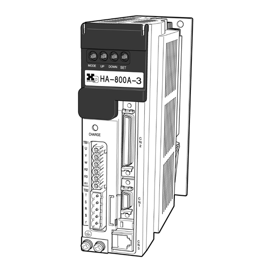
Page 36: Name And Function Of Each Part Of A Display Panel
1-9 Name and function of each part of a display panel Name and function of each part of a display panel The following explains the operation part on the front side of this driver as well as each function provided on the operation part. HA-800A-1/HA-800A-3/HA-800A-6 Cover is open Maintenance connector... - Page 37 1-9 Name and function of each part of a display panel HA-800A-24 Device number setting switch (SW5) Cover is open Maintenance connector Set the device number of each driver when multiple drivers are Do not connect. connected for communication. Waveform monitoring connector Communication setting switch (SW6) (CN9) Set the terminating resistance when...
- Page 38 1-9 Name and function of each part of a display panel Appe 1-17...
- Page 39 Chapter 2 Installation/wiring Receiving inspection, environment, power wiring, noise suppression and connector wiring are explained in this chapter. Receiving inspection ·························································· 2-1 Installation location and installation ········································ 2-2 Connecting power cables ···················································· 2-5 Suppressing noise ··························································· 2-14 Wiring the driver and motor ················································ 2-17 Wiring the host device ······················································...
-
Page 40: Receiving Inspection
2-1 Receiving inspection Receiving inspection After unpacking, check the items described below. Check procedure Check for damage. If any damage is found, immediately contact the supplier or store where you purchased your driver. Check if the driver is what you ordered. Check the model code shown below the display panel on the front face of this driver. -
Page 41: Installation Location And Installation
2-2 Installation location and installation Installation location and installation Install this driver in a manner meeting the conditions specified below. Installation environment 0 to 50℃ Store the driver in a cabinet. The temperature in the cabinet may be higher than the outside Operating air temperature due to power losses of the housed devices, size of the cabinet, etc. -
Page 42: Installation Procedure
2-2 Installation location and installation Installation procedure [HA-800A-1, HA-800A-3, HA-800A-6] Install the driver using 2 mounting holes provided at the back. The wall on which to install the driver should be made of an iron sheet of 2mm or more in thickness. Screw a M4 screw into the middle of the tapped hole provided at the bottom of the mounting surface. - Page 43 2-2 Installation location and installation [HA-800A-24] An iron sheet of 5 mm or more in thickness is recommended for the wall on which to install the driver. Screw an M5 screw into the middle of the mounting hole (U-shaped) provided at the bottom of the driver.
-
Page 44: Connecting Power Cables
2-3 Connecting power cables Connecting power cables The following explains how to connect the power supply to this driver. Before connecting the power cable to the HA-800A driver, completely unplug the power cable from the main power supply. Failure to do so may result in electric shock during the connection work. -
Page 45: Connecting Power Cables
2-3 Connecting power cables [single-phase 100V input Min. allowable wire size (mm Driver HA-800A-1 HA-800A-3 HA-800A-6 Combined FHA-8C FHA-25C SHA25 actuator FHA-11C FHA-17C FHA-32C MAB09 FHA-14C Combined motor Main circuit R,S,T 0.75 1.25 power Control circuit r, s 0.75 1.25 1.25 power Motor... - Page 46 2-3 Connecting power cables HA-800-24 3-phase power supply (200V) HA-800A Circuit breaker Magnetic switch Noise filter Terminal block for power connection Terminal Screw Crimp terminal Reference name size external diameter Round crimp terminal (R-type) 3.5-R4 (J.S.T. Mfg. Co., Ltd) R,S,T, φ8mm 5.5-4NS (J.S.T.
-
Page 47: Protecting Power Lines
2-3 Connecting power cables Protecting power lines Be sure to use a circuit breaker (MCB) in the power line to protect the power line. Select an appropriate circuit breaker from the table below. Input 200V 200V 200V 200V 100V 200V 200V 200V voltage... -
Page 48: Power On And Off Sequences
2-3 Connecting power cables Power ON and OFF sequences Provide a sequence circuit that cuts off the main circuit power ON/OFF switch in response to an emergency stop signal, etc. If an alarm signal has been assigned to an output signal, also provide a sequence circuit that cuts off the main circuit power ON/OFF switch in response to the alarm output. - Page 49 2-3 Connecting power cables Servo-OFF sequence (HA-800A-1, -3, -6) Input signal: CN2-2 servo-ON (S-ON) 1ms (typ) Motor excitation Excitation ON Excitation OFF 2ms (typ) Output signal: Operation preparation complete 5ms (typ) Dynamic brake Disable (DB enabled, SP55 = 1) Enable Disable Dynamic brake (Dynamic brake disabled)
- Page 50 2-3 Connecting power cables Power OFF sequence (HA-800A-1, -3, -6) Create a sequence program for the host device so that the power to this driver will be turned OFF at the timings shown below. 5s (min) Control circuit power 0ms (min) Main circuit power 5 minutes (max) Output signal:...
- Page 51 2-3 Connecting power cables Servo-OFF sequence (HA-800A-24) Input signal: CN2-2 servo-ON (S-ON) 1ms (typ) Excitation ON Motor excitation Excitation OFF 2ms (typ) Output signal: Operation preparation complete Dynamic brake Disable (Dynamic brake disabled* (DB enabled, SP55 = 1* Enable *2: Make sure to use HA-800A-24 by setting [SP55: DB enable/disable setting] to 1 (default setting). *3: The dynamic brake operates interlinked to the main circuit power.
- Page 52 2-3 Connecting power cables Power OFF sequence (HA-800A-24) Create a sequence program for the host device so that the power to this driver will be turned OFF at the timings shown below. 5s (min) Control circuit power 0ms (min) Main circuit power 200ms (typ) Output signal: Servo ON input enable...
-
Page 53: Suppressing Noise
2-4 Suppressing noise Suppressing noise The main circuit of this driver uses a power element (IPM) based on PWM control. Switching noise generates due to sudden changes in current/voltage that occur when this element is switched. If wiring and grounding are inappropriate, other external devices may malfunction or radio noise may generate. This driver also has a CPU and other built-in electronic circuits. -
Page 54: Installing Noise Filters
2-4 Suppressing noise Installing noise filters Use of noise filters is recommended to prevent malfunctions caused by impulse noise that may enter from the power line and also to prevent noise generating inside the driver from emitting to the power line. - Page 55 2-4 Suppressing noise Install the noise filters and this driver as close as possible with one another. Also install noise filters to the power source cables of electric devices other than this driver in the same manner. In particular, always install noise filters to sources of high-frequency, such as electric welders and electrical-discharge processing machines.
-
Page 56: Wiring The Driver And Motor
2-5 Wiring the driver and motor Wiring the driver and motor The following explains how to wire this driver and motor. Connecting the motor Connect the motor by connecting the U, V and W terminals of the TB1 connector, as shown below. Refer to the actuator manual to check the phase order of motor cable wires beforehand, and connect each pair of terminals that have the same symbol. -
Page 57: Connecting The Encoder
2-5 Wiring the driver and motor Connecting the encoder To connect the encoder, connect the CN1 connector, as shown below. For the encoder signal wire, use a twisted pair shield cable with a wire size of 0.3mm or larger and having the necessary number of cores. -
Page 58: Wiring The Host Device
2-6 Wiring the host device Wiring the host device The following explains wiring of this driver and host device. Connecting the host device To connect the host device, connect the CN2 connector, as shown below. For the I/O signal cable, use a twisted pair shield cable or twisted pair whole-shield cable with a wire size of 0.2mm (AWG24) and having the necessary number of cores. -
Page 59: Connecting The Personal Computer (Psf-800)
2-6 Wiring the host device Connecting the personal computer (PSF-800) To connect to the personal computer, use dedicated communication cable or refer to the following pin layout. Dedicated communication cable: EWA-RS03 (option) Cable length: 1.6m PSF-800 communication connector (CN3) Connector Manufacturer Hirose Electric Co., Ltd. - Page 60 2-6 Wiring the host device 2-21...
- Page 61 Chapter 3 Startup Startup procedures to be followed when the driver is used for the first time, from receiving inspection to operation of the actual system, are explained in this chapter. Startup procedures ···························································· 3-1 Turning ON the power for the first time ··································· 3-3 Operation check with the actuator alone ·································...
-
Page 62: Startup Procedures
3-1 Startup procedures Startup procedures The following explains the procedures to start up this driver. Shut off the electric power source on the plant side before any wiring works are carried out. Once the electric power on the plant side is supplied to the system, do not perform any wiring WARNING works. -
Page 63: Startup Procedures
3-1 Startup procedures Startup procedures Key startup procedures are as follows: Check before turning ON the power Refer to: [Turning ON the power for the first time] (P3-3) for the first time Operation check with the actuator Refer to: [Operation check with the actuator alone in the actual control mode alone] (P3-9) Appe... -
Page 64: Turning On The Power For The First Time
3-2 Turning ON the power for the first time Turning ON the power for the first time The following explains the startup procedure when turning ON the power for the first time. (1) Be sure to perform a trial run before commencing the normal operation. -
Page 65: Details On Control Power Supply On
3-2 Turning ON the power for the first time Details on control power supply ON The driver's internal process sequence to be implemented upon power ON varies depending on the connected actuator. (1) 17-bit absolute encoder (17-bit encoder incremental model) (SHA series, FHA-Cmini series) combination (P3-4) (2) When a 13-bit absolute encoder (FHA-C series) is combined (P3-5) (3) When a 4-wire incremental encoder (FHA-Cmini series) is combined (P3-6) - Page 66 3-2 Turning ON the power for the first time (2) When a 13-bit absolute encoder (FHA-C series) is combined Turn ON the control circuit power. Check the input voltage and multi revolution data of the absolute encoder. Normal Abnormal MODE DOWN The system switches to the status display mode.
- Page 67 3-2 Turning ON the power for the first time (3) When a 4-wire incremental encoder (FHA-Cmini series) is combined Turn ON the control circuit power. Check the driver and actuator combination. Normal Abnormal MODE DOWN Appe The system switches to the status display mode. The default setting is to display the motor rotation speed.
- Page 68 3-2 Turning ON the power for the first time (4) When a 4-wire incremental encoder (FHA-C series) or 14-wire incremental encoder is combined Turn ON the control circuit power. Normal Abnormal MODE DOWN The system switches to the status display mode. The default setting is to display the motor rotation speed.
-
Page 69: Troubleshooting Upon Power On
3-2 Turning ON the power for the first time Troubleshooting upon power ON Description Description Check item Estimated cause Reference of problem operation Power ON The situation improves when Insufficient input voltage or connector poor power connection unplugged. Defective driver The LEDs do not turn ON. -
Page 70: Operation Check With The Actuator Alone
3-3 Operation check with the actuator alone Operation check with the actuator alone The following explains the operation check procedure on the motor alone before the motor is assembled into the system. Be sure to perform a trial run before commencing the normal operation. In a trial run, separate the actuator from the machine/system and operate the actuator alone (under no load). -
Page 71: Troubleshooting At Operation Check
3-3 Operation check with the actuator alone Troubleshooting at operation check Position control mode Description Refere- Operation Check item Estimated cause of problem Servo-ON The servo Is the motor wire connected Poor motor wire connection P2-17 input does not lock. correctly? Is the operation preparation 1.The servo-ON signal has not been... - Page 72 3-3 Operation check with the actuator alone Speed control mode Description Refere- Operation Check item Estimated cause of problem Servo-ON The servo Is the motor wire connected Poor motor wire connection input does not lock. correctly? P2-17 Is the operation preparation 1.The servo-ON signal has not been completed? input.
- Page 73 3-3 Operation check with the actuator alone Torque control mode Description Refere- Operation Check item Estimated cause of problem Servo-ON The servo Is the motor wire connected Poor motor wire connection input does not lock. correctly? P2-17 Is the operation preparation 1.The servo-ON signal has not been completed? input.
-
Page 74: Operation Check With The Actual System
3-4 Operation check with the actual system Operation check with the actual system The following explains the operation checking procedure to be performed using the applicable system assembled with the motor. If this product is applied to any facility that affects life or may trigger material losses, install safety devices so that accidents will not occur even when the output control is disabled due to damage. -
Page 75: Troubleshooting At Actual Operation Check
3-4 Operation check with the actual system Troubleshooting at actual operation check Description of Operation Check item Estimated cause Refere-nce problem Auto-tuning Significant Is the startup or shutdown Host controller setting error vibration does time too short? not decrease P9-11 even after Is the load inertia too big? Actuator selection error... -
Page 76: Manual Gain Adjustment Method
3-5 Manual gain adjustment method Manual gain adjustment method If sufficient adjustment could not be achieved by auto-tuning, manual adjustment can be performed using various parameters. When manually adjusting the servo gain, adjust the gains of individual servos one by one. Check the response characteristics using the HA-800 driver monitor software PSF-800 waveform monitoring. -
Page 77: Speed Control
3-5 Manual gain adjustment method Adjustment details Speed loop gain (AJ01) This parameter is used to determine the response of the speed loop. Increasing the set value of this parameter improves the response, but increasing the value excessively causes the mechanical system to vibrate easily. On the other hand, a lower response of the speed loop eliminates vibration but it may cause the response to drop. - Page 78 3-5 Manual gain adjustment method Gradually increase the speed loop gain (AJ01) to the extent that the machine does not vibrate or produce abnormal sound, and once vibration or abnormal sound is detected decrease the gain slightly. Gradually decrease the speed loop integral compensation (AJ02) to the extent that the machine does not vibrate or produce abnormal sound, and once vibration or abnormal sound is detected increase the compensation slightly.
-
Page 79: Applied Servo Gain Adjustment Function
3-5 Manual gain adjustment method Applied servo gain adjustment function The feed-forward control function can be adjusted with the applied adjustment function. Normally, you should first use the above manual gain adjustment methods in [Position control] (P3-15).Only when these adjustments do not provide satisfactory results you should use the applied adjustment function. - Page 80 3-5 Manual gain adjustment method Block diagram of feed-forward control function HA-800A driver Mechanical load system Feed-forward Differen- control part tiation Position Position Speed control Power control part command part amplifier Actuator Speed feedback Position feedback Encoder Parameters The following parameters are used for feed-forward control. Parameter No.
- Page 81 3-5 Manual gain adjustment method Feed-forward gain (AJ03) ・Adjustment method If the feed-forward gain is set too high, the command is achieved more quickly. However, an excessively high gain leads to mechanical shock or vibration (hunting). Set [AJ03L Feed-forward gain] in the range [0 to 100].Set the feed-forward gain to around 50 and check the response.
- Page 82 3-5 Manual gain adjustment method Spring constant compensation factor (AJ23) ・Normal use Variation in the actuator spring constant is compensated for. Feed-forward control is performed based on the value set here. Set this factor to 100% in normal use. When [SP69: Feed-forward control function setting] is 0 or 1, the setting has an effect.
-
Page 83: Normal Operation
3-6 Normal operation Normal operation This driver operates according to commands received from the host device. No special procedures are required in normal operations. The following explains the notices when performing normal operations as well as daily maintenance/inspection. Notices for normal operations (1) Do not change wirings while the power is supplied. -
Page 84: Periodically Replaced Parts
3-6 Normal operation Periodically replaced parts A detection circuit is provided for the following replacement parts of this driver so that any part that can no longer operate correctly can be identified. However, it is recommended that each part be replaced at the specified timing listed below. -
Page 85: How To Replace The Backup Battery
3-6 Normal operation Built-in capacitor of actuator Data retention time Data retention Approx. 30 min. after the time power is cut off After 3 h of charging, ambient Conditions temperature 25℃, axis stopped How to replace the backup battery If [UA 91: Low battery power] displays, replace the battery by following the procedure below: Open the operation panel cover. - Page 86 3-6 Normal operation 3-25...
- Page 87 Chapter 4 Encoder system The encoder configuration is different depending on the actuator model. Details of each actuator are explained in this chapter. Overview of encoders ························································· 4-1 17-bit absolute encoder ······················································ 4-4 13-bit absolute encoder ···················································· 4-15 Incremental encoder ························································ 4-25...
-
Page 88: Overview Of Encoders
4-1 Overview of encoders Overview of encoders A different type of encoder is embedded in the actuator according to the actuator model. Accordingly, wirings, signal exchange with the driver, etc., vary depending on the applicable model. Details are explained below for each encoder type. Check the section corresponding to your actuator. Encoder type Actuator model Driver model... - Page 89 4-1 Overview of encoders The specifications of encoders that can be connected to the HA-800A driver are shown below. Select an applicable driver model according to the actuator used and the applicable encoder specification. 13-bit 14-wire 4-wire wire-saving Item 17-bit absolute encoder *1 absolute incremental incremental encoder...
- Page 90 4-1 Overview of encoders 13-bit 14-wire 4-wire wire-saving Item 17-bit absolute encoder *1 absolute incremental incremental encoder encoder encoder Actuator SHA series SHA20 and FHA-C FHA-Cmini FHA-C RSF/RKF model (excluding FHA-Cmini series series series series SHA20) series HA-800A current 33-bit data 33-bit data 33-bit data value data output...
-
Page 91: 17-Bit Absolute Encoder
4-2 17-bit absolute encoder 17-bit absolute encoder If AL81 (system failure), AL82 (single rotation data error) or AL83 (multi revolution data error) occurs due to a loss of absolute position or error, be sure to reset the origin. Failure to do so may result in unexpected operations. CAUTION Features The SHA series (excluding SHA20) is equipped with a multi revolution-type 17-bit magnetic absolute... - Page 92 4-2 17-bit absolute encoder Actuator HA-800A driver Data calculation part Communication Single control part revolution detection part Backup battery Multi revolution detection Communication part control part Angle compensation data Backup capacitor Block diagram of actuator/encoder and driver Standard connection A connection example of an actuator of 17-bit absolute encoder model with a HA-800A driver is shown.
-
Page 93: Startup
4-2 17-bit absolute encoder Startup Parameters that must be set Parameter Name Function Set the phase A and B pulses to be output to the encoder monitor output terminals (CN2-42 to 48) when the motor shaft of the 17-bit absolute encoder turns one revolution. Encoder monitor output SP61 Setting range: 1 to 8,192 (Default: 8192) - Page 94 4-2 17-bit absolute encoder Setting the parameters Set [SP61: Encoder monitor output pulses] and [SP67: Output shaft divide function setting*] according to the method used, then turn the power OFF, then ON again to put the parameter into effect. For details, refer to [SP61: Encoder monitor output pulses] (P8-11), [SP67: Output shaft divide function setting] (P8-13), and [Output signal pulses] (P4-11).
-
Page 95: Origin Setting
4-2 17-bit absolute encoder Origin setting Perform the following to set the origin (read the current value data at the mechanical origin position) in order to link the actuator driver and the mechanical origin. (1) Move the actuator to the target mechanical origin position via a JOG operation, manually, or using the various host controller functions. -
Page 96: Data Output
4-2 17-bit absolute encoder Data output Outputting the current value data from the pins CN2-40 and 41 This is used to acquire the current value data in order to manage the absolute position with the absolute encoder. The current value of the 17-bit absolute encoder is constantly output cyclically. Data of bits 0 to 32 (including the sign) is divided into 9 parts and sent. - Page 97 4-2 17-bit absolute encoder Model Setting Output range Unit FHA-C series -33554432 to 33554431 SHA-SG/HP series -4294967296 to 4294967295 FHA-Cmini series SP67=0 -4294967296 to 4294967295 SP67=1 -23592960 to 23592960 pls (×0.01deg equivalent) SHA-CG SP67=2 -235929600 to 235929600 pls (×0.001deg equivalent) SP67=3 -2359296000 to 2359296000 pls (×0.0001deg equivalent)
- Page 98 4-2 17-bit absolute encoder Example: The current value is 1234567 (0012D687h) 0 1 1 1 0 1 0 0 0 0 First 0 0 0 0 1 0 1 0 0 0 Second 0 0 1 1 0 1 1 0 0 0 Third 0 1 0 1 1 0 0 1 0 0 Fourth...
- Page 99 4-2 17-bit absolute encoder 131,072 ÷ 4 = 32,768 Phase A, B and Z incremental output waveforms For FWD rotation, the phase A signal is output with an advance of 90° relative to the phase B signal. For REV rotation, the phase A signal is output with a delay of 90° relative to the phase B signal.
-
Page 100: Remedial Actions For Errors/Warnings
4-2 17-bit absolute encoder Remedial actions for errors/warnings Remedial action for error Name Description Cause Action AL50 Encoder signals (1) Disconnected encoder signal (1) Repair the wire. Encoder have been cut off. wire (2) Connect connector disconnection (2) Poor contact/connection properly. - Page 101 4-2 17-bit absolute encoder Name Description Cause Action AL86 Data could not be (1) Disconnected encoder signal (1) Repair the wire. Communication received in at least wire (2) Connect connector error 4 consecutive (2) Poor contact/connection properly. communications encoder signal connector (3) Provide noise suppression between the (3) Malfunction due to external...
-
Page 102: 13-Bit Absolute Encoder
4-3 13-bit absolute encoder 13-bit absolute encoder If AL53 (system failure), AL54 (multi revolution counter overflow) or AL55 (multi revolution data error) generates due to a loss of absolute position or error, be sure to reset the origin. Failure to do so may result in unexpected operations. CAUTION Features The FHA-C series is equipped with a multi revolution-type 13-bit optical absolute encoder. - Page 103 4-3 13-bit absolute encoder Standard connection A connection example of an actuator of 13-bit absolute encoder model with a HA-800A driver is shown. AC Servo Actuator HA-800A-*A FHA-C series R1 and R3 are shorted. White When using an external regenerative resistor, Black keep R1 and R3 open and connect the regenerative resistor between R1 and R2.
-
Page 104: Startup
4-3 13-bit absolute encoder Startup Startup procedures Setting the backup battery Open the operation panel cover, and confirm that the backup battery is set. If not, set one by referring to [How to replace the backup battery] (P3-24). Initializing the absolute encoder system When the power supply is turned ON for the first time, [AL53: System failure] generates. -
Page 105: Origin Setting
4-3 13-bit absolute encoder Origin setting Perform the following to set the origin (read the current value data at the mechanical origin position) in order to link the actuator driver and the mechanical origin. (1) Move the actuator to the target mechanical origin position via a JOG operation, manually, or using the various host controller functions. -
Page 106: Data Output
4-3 13-bit absolute encoder Data output Outputting the current value data from pins CN2-40 and 41 The current value data is output with the same technique as for a 17-bit absolute encoder. For details, refer to [Data output] (P4-9). Outputting the current value data from the pins CN2-42 to 47 (HA-655 driver mode) Position data is output from the encoder phase A, B and Z signal output ports as with any HA-655 series driver. - Page 107 4-3 13-bit absolute encoder Absolute position The absolute position is output using 2 phase signals having a phase difference of 90°. If the multi revolution data is positive, the phase A signal is output with an advance of 90° relative to the phase B signal.
- Page 108 4-3 13-bit absolute encoder Encoder phase A, B and Z signal outputs When the motor shaft equipped with a 13-bit absolute encoder turns, incremental phase A, B and Z signals are output to the pins CN2-42 to 48. Number of output pulses When the motor shaft turns one revolution, 2,048 pulses are output.
- Page 109 4-3 13-bit absolute encoder Phase A, B and Z output signal waveforms For FWD rotation, the phase A signal is output with an advance of 90° relative to the phase B signal. For REV rotation, the phase A signal is output with a delay of 90° relative to the phase B signal.
-
Page 110: Remedial Actions For Errors/Warnings
4-3 13-bit absolute encoder Remedial actions for errors/warnings Remedial action for error Name Description Cause Action AL50 Encoder signals (1) Disconnected encoder signal (1) Repair the wire. Encoder have been cut wire (2) Connect the connector properly. disconnection off. (2) Poor contact/connection of (3) Review the actuator installation encoder signal connector location and cooling system. - Page 111 4-3 13-bit absolute encoder Remedial action for warning Name Description Cause Action UA91 The backup (1) Voltage drop due to consumption (1) Replace with a new battery. Battery battery voltage of backup battery (2) Repair the wire. voltage low has dropped to (2) Short-circuit the encoder battery (3) Replace the HA-800A driver.
-
Page 112: Incremental Encoder
4-4 Incremental encoder Incremental encoder The incremental encoder has a relatively simple structure where pulses are output according to changes in rotation angle. However, it has one drawback of causing loss of current position data when the power supply is cut off, and therefore position control requires originating operation using a separately provided origin sensor. - Page 113 4-4 Incremental encoder 14-wire wire-saving incremental encoder model AC Servo Actuator RSF/RKF series HA-800A-*B White Black R1 and R3 are shorted. When using an external regenerative resistor, keep R1 and R3 open and Green/ connect the regenerative Yellow resistor between R1 and Shield If you are not using an Be sure to connect to...
-
Page 114: Startup
4-4 Incremental encoder Startup Parameters that must be set Nothing in particular. Startup procedures Initializing the incremental encoder system With incremental encoder systems using FHA-Cmini, FHA-C or RSF/RKF series actuators, driver feedback pulses are reset to 0 (initialized) when the driver power supply is turned ON. Checking originating operation In order to link the actuator driver and the mechanical origin to each other, either perform originating using the originating function of the host controller, or manage the coordinate data at... - Page 115 4-4 Incremental encoder Data output Encoder phase A, B and Z signal outputs When the motor shaft equipped with an encoder turns, incremental phase A, B and Z signals are output to the pins CN2-42 to 48. Number of output pulses The numbers of phase A and B signal output pulses per motor shaft revolution vary depending on the encoder resolution.
-
Page 116: Remedial Action For Error
4-4 Incremental encoder Remedial action for error Name Description Cause Action AL50 Encoder (1) Disconnected encoder signal (1) Repair the wire. Encoder signals have wire (2) Connect the connector properly. disconnection been cut off. (2) Poor contact/connection of (3) Review the actuator installation encoder signal connector location and cooling system. - Page 117 Chapter 5 I/O signals Details of I/O signal conditions and signal functions are explained in this chapter. I/O signal list ····································································· 5-1 Input signals: System parameter SP00 to SP16 ······················· 5-3 Details of input signals ························································ 5-9 Inputs in each control mode ··············································· 5-16 Output signals: System parameter SP20 to SP26 ···················...
-
Page 118: I/O Signal List
5-1 I/O signal list I/O signal list This unit communicates with the host device via the CN2 connector. The following explains the I/O signals used in this communication. Pin numbers and names of I/O signals The CN2 pin numbers and corresponding signal names are shown in the table below. Functions can be set and assigned to input signals (pins 3 to 7, 9 and 10) and output signals (pins 16 to 22) using system mode parameters 1 and 2. -
Page 119: Models Of I/O Signal Connector Cn2
5-1 I/O signal list Models of I/O signal connector CN2 The models of CN2 connector are shown below: Connector Cover Manufacturer Model 10150-3000PE 10350-52F0-008 Appe... -
Page 120: Input Signals: System Parameter Sp00 To Sp16
5-2 Input signals: System parameter SP00 to SP16 Input signals: System parameter SP00 to SP16 The following explains the input signals. The input signals are explained in the order of pin numbers of CN2. Signals corresponding to system parameters SP00 to SP16 can be assigned to pin numbers 3 to 7, 9 and 10. ... -
Page 121: Input Signal Connection Circuit
5-2 Input signals: System parameter SP00 to SP16 Input signal connection circuit The following explains how to connect the input signal port to the host device. This driver has 8 input signal ports as shown below. Specifications of input ports Voltage: DC24V ±... - Page 122 5-2 Input signals: System parameter SP00 to SP16 Input signal function (logic) Input signal status from host Opt-isolator ON Opt-isolator OFF HA-800 HA-800 IN-COM IN-COM Circuit status 0:Normally open (contact A) Enable Disable Logic Logic NO setting 1:Normally closed (contact B) Disable Enable Logic NC...
-
Page 123: Input Signal List
5-2 Input signals: System parameter SP00 to SP16 Input signal list The input signals to which 3 to 7, 9 and 10 pins of CN2 can be assigned are as shown below. Set the values on the following page to the input signals to be used (Parameter Nos. SP00 to 16) and specify the input pins to be assigned and the corresponding signal logic. -
Page 124: List Of Parameter Set Values
5-2 Input signals: System parameter SP00 to SP16 Multiple input signals can be assigned to one pin. Unnecessary signals should be deleted from the pin assignments. If unnecessary signals are assigned, the system will not operate as expected. For the input signal servo-ON, the assigned pin or the logic cannot be changed. ... - Page 125 5-2 Input signals: System parameter SP00 to SP16 The values of PSF-800 items show the values displayed in the PSF-800 communication software parameter window. For details on the method for setting input signals using the PSF-800, refer to [Assigning I/O signals] (P10-13).
-
Page 126: Details Of Input Signals
5-3 Details of input signals Details of input signals The following explains the details of input signals. For the signal logic, refer to P5-5. * The setting change of the system parameters (SP00 to 79) is enabled by reconnecting the control power supply after changing the setting. - Page 127 5-3 Details of input signals P: Position control S: Speed control T: Torque control Applicable Parameter Signal name Default Function control (Abbreviation) setting mode SP03 FWD inhibit This parameter sets the limit of moving in forward and 0104 P.S.T (FWD-IH) reverse directions.
- Page 128 5-3 Details of input signals P: Position control S: Speed control T: Torque control Applicable Parameter Signal name Default Function control (Abbreviation) setting mode SP05 FWD enable This parameter determines the rotary operation status 0006 (FWD-EN) of the actuator relative to the speed command value according to the input status of FWD/REV enable signals when the actuator is operating in the speed control mode.
- Page 129 5-3 Details of input signals P: Position control S: Speed control T: Torque control Applicable Parameter Signal name Default Function control (Abbreviation) setting mode SP07 FWD selection This parameter determines the operating status of the 0006 (FWD-SEL) actuator relative to the torque command value according to the input status of FWD/REV selection signals while the actuator is operating in the torque control mode.
- Page 130 5-3 Details of input signals P: Position control S: Speed control T: Torque control Applicabl Parameter Signal name Default Function e control (Abbreviation) setting mode SP11 Internal speed When the actuator is operating in the position control 0000 limit selection mode, the speed can be limited to the speed specified by an external speed command voltage or the speeds (SPD-LMT1)
- Page 131 5-3 Details of input signals P: Position control S: Speed control T: Torque control Applicable Parameter Signal name Default Function control (Abbreviation) setting mode SP13 Torque limit The driver can limit the output torque to the value set 0000 (TRQ-LMT) in [AJ11: Torque limit value] or less.
- Page 132 5-3 Details of input signals P: Position control S: Speed control T: Torque control Applicable Parameter Signal name Default Function control (Abbreviation) setting mode SP15 Control mode The driver can operate in one of three control modes 0008 P.S.T selection of position control, speed control, and torque (CON-SEL) control.With the control mode selection, you can...
-
Page 133: Inputs In Each Control Mode
5-4 Inputs in each control mode Inputs in each control mode The following explains the input signals corresponding to pins 26 to 34 of the CN2 connector for each control mode (position command mode, speed command mode, and torque command mode). Position command mode Pulse train input connection pattern and power supply voltage This parameter selects line driver connection, +24V input voltage or +5V open collector. - Page 134 5-4 Inputs in each control mode Supply voltage: +5V ± 10% Input current (I): 16 mA, standard (20 mA or less) Provided by the customer 2.2k 75Ω 2.2k FWD+ FWD- Forward command pulse signal input 75Ω REV+ REV- Reverse command pulse signal input ...
- Page 135 5-4 Inputs in each control mode Use the negative logic for command pulse signals. A negative logic circuit determines a condition of low voltage level (OFF) as 1 and that of high voltage level (ON) as 0. If [2-pulse train] is selected, the opt-isolator to which no pulse is input should be in OFF state.
- Page 136 5-4 Inputs in each control mode Pulse time condition For command pulses, input those satisfying the following conditions. The maximum response frequency of the HA-800A's command pulse input circuit is 1MHz (or 200kHz if the 2-phase pulse train or open collector is selected). Input command pulses within a duty range of 50 ±...
-
Page 137: Speed Command Mode
5-4 Inputs in each control mode Speed command mode Example of speed command input circuit Input impedance: 68kΩ ◆ Example of command using a variable resistor ◆ Example of command using an operation amplifier 1kΩ 68kΩ 68kΩ SPD-CMD SPD-CMD 10kΩ SPD-GND SPD-GND 1kΩ... -
Page 138: Torque Command Mode
Torque command mode Torque commands control the motor torque. The output torque of the actuator ® is subject to a HarmonicDrive speed reducer loss of 20 to 30%. If the actuator's torque must be controlled accurately, provide a control system that uses a torque sensor on the output shaft. - Page 139 5-4 Inputs in each control mode FWD selection is enabled REV selection is enabled torque +command -command torque voltage (V) voltage (V) -command +command voltage (V) voltage (V) torque torque Appe 5-22...
-
Page 140: Output Signals: System Parameter Sp20 To Sp26
5-5 Output signals: System parameter SP20 to SP26 Output signals: System parameter SP20 to SP26 The following explains the details of output signals. The output signals are explained in the order of pin numbers of CN2. Desired output signals can be set to pin No. -
Page 141: Output Signal Connection Circuit
5-5 Output signals: System parameter SP20 to SP26 Output signal connection circuit Specifications of output ports Open-collector output opt-isolator insulation Voltage: DC24V or less Current: 40 mA or less/port OUT1 Output 1 OUT2 Output 2 OUT3 Output 3 OUT4 Output 4 OUT5 Output 5 Output 6... -
Page 142: Output Signal List
5-5 Output signals: System parameter SP20 to SP26 Output signal list The output signals that can be assigned to outputs 1 to 7 are explained below. The signals that can be used are limited by the number of connector pins. Accordingly, select desired signals and assign them to output pins if you wish to use signals other than signals set as default. -
Page 143: Details Of Output Signals
5-6 Details of output signals Details of output signals The following explains the output signals assigned to outputs 1 to 7 (pins 16 to 22 of CN2). * The setting change of the system parameters (SP00 to 79) is enabled by reconnecting the control power supply after changing the setting. - Page 144 5-6 Details of output signals Applicable Signal name Function control value (Abbreviation) mode Battery voltage When an absolute encoder is combined, this signal indicates that the P.S.T multi revolution data backup voltage is low. For details, refer to the (BAT-LOW) table below.
-
Page 145: Monitor Output
5-7 Monitor output Monitor output The following explains how to output the encoder signal monitor output and current value data output signals from the CN2 connector and to output the speed, current analog monitor and status digital monitor signals from the CN9 connector. Encoder output The encoder's phase A, B, and Z signals are output via a line driver (26LS31). -
Page 146: Analog Waveform Monitoring
5-7 Monitor output Analog waveform monitoring Monitored analog speed/current waveforms can be output from the CN9 connector. An optional monitor cable is available for observing waveforms using an oscilloscope. Model code: EWA-MON01-JST4 Speed monitor: SPD-MON The port outputs a voltage signal proportional to the motor rotation speed (speed input factor per 10V). -
Page 147: Digital Signal Monitor
5-7 Monitor output Digital signal monitor The signal waveform set in [SP40: CP3 output signal setting] (For details, refer to P8-4) is output. The output voltage is 0V for Low and 3.3V for High. Take note that the output remains unstable after the power is input until the [Servo-ON input enable: S-READY] signal is output. -
Page 148: Connection Example In Control Mode
5-8 Connection example in control mode Connection example in control mode Connection example with default settings HA-800A 2.2k Terminal voltage (Vin): Set to 3.5V or more. 2.2k Am26LS31 (EIA422A) or equivalent FWD+ FWD command pulse FWD- signal input REV+ REV command pulse REV- signal input Power input... -
Page 149: Connection Example In Position Control Mode
5-8 Connection example in control mode Connection example in position control mode The line driver command pattern in the position control mode is shown in the connection example for 2-pulse train. HA-800A 2.2k Terminal voltage (Vin): Set to 3.5V or more. 2.2k Am26LS31 (EIA422A) or equivalent FWD+... -
Page 150: Connection Example In Speed Control Mode
5-8 Connection example in control mode Connection example in speed control mode A connection example in the speed control mode is shown. HA-800A Speed command signal SPD-CMD input SPD-GND Speed command signal input ground IN-COM External DC24V 2.2k power supply S-ON Servo-ON Power input... -
Page 151: Connection Example In Torque Control Mode
5-8 Connection example in control mode Connection example in torque control mode A connection example in the torque control mode is shown. HA-800A TRQ-CMD Torque command signal input TRQ-GND Torque command signal input ground Power input Noise filter AC200V IN-COM External power DC24V (50/60Hz) - Page 152 5-8 Connection example in control mode Appe 5-35...
-
Page 153: Chapter 6 Panel Display And Operation
1-10 Chapter 6 Panel display and operation How to operate the display, operation buttons on the driver's front panel and overview of operation in each mode is explained in this chapter. Operating display panel ······················································ 6-1... -
Page 154: Operating Display Panel
6-1 Operating display panel Operating display panel The front display panel has a 5-digit LED display and 4 operation keys. You can perform all display, tuning, setting and other operations on this display panel. Overview of modes The display panel is operated in the 5 modes specified below. Status display mode (d00 to d15) Position/speed commands to the driver, current position information from the motor encoder, condition of cumulative pulses in the deviation counter and code number of the actuator to be... -
Page 155: Initial Panel Display
6-1 Operating display panel Initial panel display The following explains the panel display shown when the driver is started normally and while an alarm is present. Display upon control power supply ON When the driver's control power supply is turned ON, the driver model HA-800 is shown at the far right of the panel display. -
Page 156: Panel Display Hierarchy
6-1 Operating display panel Panel display hierarchy The display hierarchy of the display panel is shown below. When an alarm occurs, the display panel switches to the alarm mode, regardless of the present mode, and shows the present alarm code. Even when an alarm is present, you can still switch to other mode and check or change parameters. -
Page 157: Operation Outline Of Status Display Mode
6-1 Operating display panel Operation outline of status display mode An overview of operations in the status display mode is shown below. To prevent malfunction, a button is recognized as enabled when it has been pressed for at least 0.1 second and 1 second or less. -
Page 158: Operation Outline Of Alarm Mode
6-1 Operating display panel Operation outline of alarm mode An overview of operations in the alarm mode is shown below. To prevent malfunction, a button is recognized as enabled when it has been pressed for at least 0.1 second and 1 second or less. -
Page 159: Operation Outline Of Tune Mode
6-1 Operating display panel Operation outline of tune mode An overview of operations in the tune mode is shown below. To prevent malfunction, a button is recognized as enabled when it has been pressed for at least 0.1 second and 1 second or less. * For details on the tune mode, refer to [Tune mode] (P7-12). - Page 160 6-1 Operating display panel How to change set value Press the SET button and release it before the flickering stops (within approx. 1 second), and the change will be cancelled. Parameter set value DOWN MODE DOWN S E T MODE DOWN S E T MODE DOWN S E T...
-
Page 161: Operation Outline Of System Parameter Mode
6-1 Operating display panel Operation outline of system parameter mode An overview of operations in the system parameter mode is shown below. To prevent malfunction, a button is recognized as enabled when it has been pressed for at least 0.1 second and 1 second or less. - Page 162 6-1 Operating display panel How to set input signals (SP00 to 16) * For details on input signals, refer to P5-9. Example) Setting [SP01: Reset input setting] Change the input signal from IN2 to 3 and logical set value from 00 to 01. MODE DOWN S E T Assign to one of IN2 to...
- Page 163 6-1 Operating display panel How to set output signals (SP20 to 26) * For details on output signals, refer to P5-26. Example) Assigning [03: Alarm output] to pin 17 of CN2 Logic circuit setting 01→00 Set value of output signal 02→03 MODE DOWN S E T Set value of output signal...
- Page 164 6-1 Operating display panel How to set function extension signals (SP**) Example) Changing [SP40: CN9-CP3 output signal setting] to 2 MODE DOWN S E T Set value Press the SET button and release it before the flickering stops (within approx. 1 second), and the change will be cancelled. MODE DOWN DOWN...
-
Page 165: Operation Outline Of Test Mode
6-1 Operating display panel Operation outline of test mode An overview of operations in the test mode is shown below. To prevent malfunction, a button is recognized as enabled when it has been pressed for at least 0.1 second and 1 second or less. * For details on test mode, refer to [Chapter 9 Test mode]. - Page 166 6-1 Operating display panel 6-13...
- Page 167 1-11 Chapter 7 Status display mode/alarm mode/tune mode This chapter explains information displayed in the status display mode and alarm mode. Operations and details of servo loop gains, various judgment criteria and acceleration/deceleration time setting during speed control performed in the tune mode are explained.
-
Page 168: Status Display Mode
7-1 Status display mode Status display mode In the status display mode, position/speed commands to the driver, current position information from the motor/encoder, condition of cumulative pulses in the deviation counter, I/O signal statuses, load condition and code number of the actuator to be combined are shown, among others. These items help diagnose errors and troubles. - Page 169 7-1 Status display mode Mode No. Name Description Default Unit Details The current control mode is shown. : Position control : Speed control Control mode Torque control An approximate total power ON time is Discharge time shown. 0 to 99,999 indicates absorbed power...
-
Page 170: Details Of Status Display Mode
7-2 Details of status display mode Details of status display mode The following explains details of the status display mode. Detailed explanations for simple items are omitted. Refer to the [Status display mode list] (P7-1). d01, 02: Error pulse count display The deviation between command pulses and feedback pulses during position control is shown.d01 indicates the lower 4 digits, while d02 indicates the upper 4 digits. -
Page 171: D04: Overload Rate Display
7-2 Details of status display mode d04: Overload rate display The current overload status of the actuator (unit: %) is shown. If the value reaches 100, the overload protective function shuts off the motor current and simultaneously [AL20: Overload] is displayed. When you want to set a higher servo gain to shorten the positioning period, the higher servo gain is permitted if the overload rate remains 0 after the actual operation. -
Page 172: D05, 06: Feedback Pulse Display
7-2 Details of status display mode d05, 06: Feedback pulse display Feedback pulses from the encoder are shown. Absolute encoder: The current encoder value is shown. Incremental encoder: Cumulative feedback pulses since the power ON, multiplied by 4 d05 indicates the lower 4 digits, while d06 indicates the upper 4 digits. -
Page 173: D11: Speed Command Voltage
7-2 Details of status display mode d11: Speed command voltage The speed command input voltage (unit: V) currently input to the driver is shown. The speed command input voltage and motor rotation speed are associated by the parameter [SP51: Speed input factor]. The actuator's output shaft rotation speed is obtained by dividing motor rotation speed by the reduction ratio of the actuator. -
Page 174: D13: Applicable Actuator Code
7-2 Details of status display mode d13: Applicable actuator code The actuator applicable to this driver is indicated by a code number. The relationship of code numbers and actuators is as follows: Codes of SHA series actuators Encoder Absolute Voltage Reduction ratio 1/11 1/51... -
Page 175: D16: Regenerative Power (Ha-800-24 Only)
7-2 Details of status display mode Codes of RSF series actuators Encoder Incremental Voltage Reduction ratio 1/50 1/100 specification RSF-17A 7365 7375 RSF-20A 7465 7475 200V RSF-25A 7575 7575 RSF-32A 7665 7675 d16: Regenerative power (HA-800-24 only) It indicates absorbed power of regenerative resistor as percentage (unit: %). The value can be converted to absorbed power of resistor using the following formula. -
Page 176: Alarm Mode
7-3 Alarm mode Alarm mode In the alarm mode, present alarms and warnings as well as up to 8 most recent alarm histories and total operating hours when each alarm occurred are shown. The alarm history can also be cleared in this mode. -
Page 177: Alarm List
7-4 Alarm list Alarm list A list of alarms and warnings is shown. AL: Present alarm/warning display The driver shows the code number of the present alarm/warning. If multiple alarms (warnings) are output, all alarm (warning) codes are shown one by one at an interval of approx. -
Page 178: Ahclr: Alarm History Clear
7-4 Alarm list AHcLr: Alarm history clear The history of up to 8 most recent alarms stored in the driver is cleared. Press the SET button when [AHcLr] is displayed. [AHcLr] flickers. Press the SET button again. The alarm history is cleared and flickering of [AHcLr] stops and becomes lit. To not clear the alarm history, pressing the UP or DOWN button cancels the alarm history clear, after which the content of A8 or AL is displayed. -
Page 179: Tune Mode
7-5 Tune mode Tune mode You can read and change parameters relating to actuator operations. The following items can be changed. Mode Code Parameters Default Details AJ00 Position loop gain P7-13 AJ01 Speed loop gain P7-13 AJ02 Speed loop integral compensation P7-14 AJ03 Feed-forward gain... -
Page 180: Details Of Tune Mode
7-6 Details of tune mode Details of tune mode The following explains the details of settings in the tune mode. AJ00: Position loop gain Adjust the proportional gain of the position feedback loop. The relation between the set value and actuator operation is as follows: ... -
Page 181: Aj02: Speed Loop Integral Compensation
7-6 Details of tune mode AJ02: Speed loop integral compensation Set this parameter to reduce the speed fluctuation due to load fluctuation. The relation between the set value and actuator operation is as follows: Increasing the set value: Vibration (hunting) is eliminated and response becomes slower upon load fluctuation. -
Page 182: Aj05: Attained Speed Judgment Value
7-6 Details of tune mode AJ05: Attained speed judgment value Set the speed condition for outputting an attained speed output signal. An attained speed judgment signal is output when the actuator's motor shaft rotation speed rises to the attained speed judgment value or above. Output signals are assigned by SP20 to 26.(P6-10) Set value Function Unit... -
Page 183: Aj08 To 10: Internal Speed Command 1 To 3
7-6 Details of tune mode AJ08 to 10: Internal speed command 1 to 3 Set the speed command for speed control without using any external speed command (analog voltage speed command). This function is useful when performing a trial run or diagnosing the system using the actuator alone. -
Page 184: Aj12: Acceleration Time Constant
7-6 Details of tune mode AJ12: Acceleration time constant Set the time over which the actuator will accelerate from the standstill state to the value set in function extension mode parameter [SP51: Speed input factor] during speed control. Set value Function Unit Default... -
Page 185: Aj14: External Speed Command Offset
7-6 Details of tune mode AJ14: External speed command offset During speed control, the motor may rotate slightly even when the input command voltage is set to 0V. This problem may occur when the external command input voltage has an offset of a few mV. External speed command offset is a function that absorbs this error to prevent slight rotation of the motor. -
Page 186: Aj20: Feed-Forward Filter
7-6 Details of tune mode AJ20: Feed-forward filter Set the filter frequency to be used in feed-forward control. Setting a higher value increases the response, but mechanical shock or vibration (hunting) will occur more easily if the value is too high. (Refer to [Applied servo gain adjustment function] (P3-18).) Set value Function Unit... -
Page 187: Aj23: Spring Constant Compensation Factor
7-6 Details of tune mode AJ23: Spring constant compensation factor Variation in the actuator spring constant used in feed-forward control is compensated for. Feed-forward control is performed based on the value set here. (Refer to [Applied servo gain adjustment function] (P3-18).) Set value Function Unit... - Page 188 7-6 Details of tune mode Appe 7-21...
-
Page 189: Chapter 8 System Parameter Mode
1-12 Chapter 8 System parameter mode Details of how to assign I/O signals and set their logics, as well as extended functions such as control mode selection, pulse input system selection and electronic gear setting, etc., are explained in this chapter. System parameter mode ·····················································... -
Page 190: System Parameter Mode
8-1 System parameter mode System parameter mode The following explains the parameters that can be operated/displayed in each operation mode. The settable parameters are explained below. Detailed explanation on function extension parameters SP40 onward are explained in this chapter. For details on other system parameters, refer to [Chapter 5 I/O signals]. - Page 191 8-1 System parameter mode Code Parameters Code Parameters Mode Mode SP67 Output shaft divide function setting SP68 System reservation SP27 System reservation SP39 SP69 Feed-forward control function setting SP70 System reservation SP79 Do not change the parameters that are in the system reserved areas. The default setting of the system reservation may vary depending on the model/version.
-
Page 192: Function Extension Parameter
8-2 Function extension parameter Function extension parameter The function extension parameters SP40 onward are explained below. For details on other system parameters, refer to [Chapter 5 I/O signals]. Parameters Name Default SP40 CP9-CP3 output signal setting SP41 Control mode switching setting SP42 Command pulse input pattern setting SP43... -
Page 193: Sp40: Cn9-Cp3 Output Signal Setting
8-2 Function extension parameter SP40: CN9-CP3 output signal setting Set the monitor output signal to pin 3 of CN9. * The setting change of the system parameters (SP00 to 79) is enabled by reconnecting the control power supply after changing the setting. Set value Description Default... -
Page 194: Sp42: Command Pulse Input Pattern Setting
8-2 Function extension parameter SP42: Command pulse input pattern setting Set the command pulse input method to be used during position control. * The setting change of the system parameters (SP00 to 79) is enabled by reconnecting the control power supply after changing the setting. (Forward command (Reverse command Set value... -
Page 195: Sp44 To 47: Electronic Gear Setting
8-2 Function extension parameter SP44 to 47: Electronic gear setting This can be set to make the displacement of the driven actuator mechanism per input pulse an integer. Use [SP14: Electronic gear selection input] to select electronic gear 1 or 2. With the SHA-CG series, electronic gear selection is enabled when [SP67: Output shaft divide function setting] is 0 (default value).For details, refer to [SP67: Output shaft divide function setting] (P8-13). -
Page 196: Sp48: Deviation Clear Upon Servo-On Setting
8-2 Function extension parameter SP48: Deviation clear upon servo-ON setting The deviation can be reset to 0 when the servo-ON signal is input. However, the position deviation data stored when the servo-ON input was OFF may be lost and the actuator may not return to its original position. - Page 197 8-2 Function extension parameter Set value Function Default Do not reverse the rotation direction. Rotates forward (clockwise rotation) with forward (FWD) command Reverse the rotation direction. Rotates in reverse (counter-clockwise rotation) with forward (FWD) command. Reverse the coordinate direction. Rotates in reverse (counter-clockwise rotation) with forward (FWD) command.
-
Page 198: Sp51: Speed Input Factor Setting
8-2 Function extension parameter SP51: Speed input factor setting Set the motor rotation speed to be applied during speed control when the input voltage set in [CN2-31 speed command input] is 10V.The relationship of input voltage and motor rotation speed is determined by the following formula based on this factor: Speed input... -
Page 199: Sp54: Status Display Setting
8-2 Function extension parameter SP54: Status display setting Set what will be displayed in the status display mode after the control power supply is turned ON. * The setting change of the system parameters (SP00 to 79) is enabled by reconnecting the control power supply after changing the setting. -
Page 200: Sp59: Angle Compensation Enable/Disable Setting
8-2 Function extension parameter SP59: Angle compensation enable/disable setting Set the angle compensation to be applied when a FHA mini series (FHA-8C/11C/14C) driver is combined with the actuator. This function analyzes the angle transmission error beforehand and compensates for this erroneous difference to improve uni-directional positional accuracy. -
Page 201: Sp64: Regenerative Resistor Selection (Ha-800-24 Only)
8-2 Function extension parameter SP64: Regenerative resistor selection (HA-800-24 only) Set this parameter on HA-800A-24 according to the connected regenerative resistor. At our factory default, the wiring is set such that set value [0: Use a built-in regenerative resistor] as well as built-in regenerative resistors are used. -
Page 202: Sp67: Output Shaft Divide Function Setting
8-2 Function extension parameter SP67: Output shaft divide function setting When using for position control combined with an SHA-CG series unit, you can set the actuator resolution. The corresponding electronic gear value is set automatically from the output shaft divide function setting and the applicable actuator. - Page 203 8-2 Function extension parameter [SP67: Output shaft divide function setting] is the function that sets the operation command resolution. It does not guarantee the precision of positioning on the output shaft. For details on the output shaft positioning precision, refer to [AC Servo Actuator SHA Series Manual].
- Page 204 8-2 Function extension parameter ○: Affected by SP67 setting x: Not affected by SP67 setting Input signals Display panel PSF-800 SP03: FWD inhibit T04: JOG operation JOG operation × × × SP04: REV inhibit T09: Auto-tuning Program operation × × ×...
-
Page 205: Sp69: Feed-Forward Control Function Setting
8-2 Function extension parameter SP69: Feed-forward control function setting This configures the feed-forward control function for position control. For details, refer to [Applied servo gain adjustment function] (P3-18). * This is available for HA-800 software version 3.x or later. * Changes to system parameter settings (SP00 to 79) are put into effect by changing the setting, then turning control power supply OFF, then ON again. - Page 206 8-2 Function extension parameter Appe 8-17...
-
Page 207: Chapter 9 Test Mode
1-13 Chapter 9 Test mode Details of how to check the system operation by auto-tuning via jogging, monitoring of I/O signals and simulated operation of output signals are explained in this chapter. Test mode ········································································ 9-1 Details of test mode ··························································· 9-2... - Page 208 9-1 Test mode Test mode In the test mode, you can monitor I/O signals and perform JOG operation, auto-tuning, etc. You can also check the connection with the host controller and operating status without having to drive the actuator. Mode Code Description Details...
-
Page 209: Details Of Test Mode
9-2 Details of test mode Details of test mode The following explains the details of the test mode. T00: I/O signal monitor The I/O statuses of assigned pins are reflected and displayed in real time. The functions of displayed pins are enabled. Press the SET button. -
Page 210: T01: Output Signal Operation
9-2 Details of test mode T01: Output signal operation Output signals can be turned ON/OFF as desired. Take note that, in this operation, the actual output signals are output and the device may be activated by the operation. Also, the operation can be done even when HA-800A is being automatically operated by the command from the host controller. -
Page 211: T02: Jog Speed Setting
9-2 Details of test mode T02: JOG speed setting Set the speed of JOG operation. Although the unit is r/min, this value indicates the actuator's motor rotation speed. The output shaft rotation speed is obtained by dividing the set value by the gear ratio. Setting range: 10 to 3000 Unit: r/min Press the SET button. -
Page 212: T03: Jog Acceleration/Deceleration Time Constant Setting
9-2 Details of test mode T03: JOG acceleration/deceleration time constant setting Set the acceleration/deceleration time constant to be applied during JOG operation. The value set here corresponds to the time over which the actuator accelerates from the standstill state to [SP51: Speed input factor] or decelerates from the speed set by the speed input factor to the standstill state. -
Page 213: T04: Jog Operation
9-2 Details of test mode T04: JOG operation The actuator can be operated regardless of the input signals from the host. Any input signal operation performed during JOG operation is ignored. The data set in [T02: JOG speed] and [T03: JOG acceleration/deceleration time] is used to perform JOG operation of the actuator. -
Page 214: T05: Parameter Initialization
9-2 Details of test mode T05: Parameter initialization The tune mode parameters (excluding AJ16 and AJ17) and system parameters are reset to their default settings. Perform this operation while the servo is OFF. After the initialization, be sure to reconnect the HA-800A driver power. -
Page 215: T06: Automatic Adjustment Of Speed Command Offset
9-2 Details of test mode T06: Automatic adjustment of speed command offset The offset for speed command input circuit is adjusted automatically. Press the SET button. The HA-800A driver displays the speed command offset currently set. The display will not switch if the button is pressed for 1 MODE DOWN S E T second or longer. -
Page 216: T07: Automatic Adjustment Of Torque Command Offset
9-2 Details of test mode T07: Automatic adjustment of torque command offset The offset for torque command input circuit is adjusted automatically. Press the SET button. The HA-800A driver displays the torque command offset currently set. The display will not switch if the button is pressed for 1 MODE DOWN S E T second or longer. -
Page 217: T08: Multi Revolution Clear
9-2 Details of test mode T08: Multi revolution clear Encoder multi revolution data can be cleared when an actuator equipped with a 13-bit absolute encoder or 17-bit absolute encoder is combined. This parameter is also used when setting the origin. With a SHA series, FHA-C absolute system, FHA-Cmini absolute system, the multi revolution counter value must be set to zero at the origin. -
Page 218: T09: Auto-Tuning
9-2 Details of test mode T09: Auto-tuning The load is estimated and auto-tuning is performed to set an optimal servo gain. Since the actuator moves to estimate the load, perform auto-tuning after thoroughly confirming safety. By default, the motor shaft moves 6,000 degrees in the clockwise direction as seen from the output shaft, then 6,000 degrees in the counter-clockwise WARNING direction. - Page 219 9-2 Details of test mode The actuator moves in forward/reverse directions for a while to estimate the load. When the load has been estimated, [run.] changes to [FInSH] to indicate that the auto-tuning is complete. Pressing the UP or DOWN button on this display MODE DOWN S E T returns the screen to the test mode number display.
-
Page 220: T10: Auto-Tuning Displacement
9-2 Details of test mode T10: Auto-tuning displacement Set the displacement of the motor during auto-tuning. Setting range: 1500 to 6000° Unit angle (°) While [T10] is displayed, press the SET button. The auto-tuning displacement is displayed. The display will not switch if the button is pressed for 1 second or longer. -
Page 221: T11: Auto-Tuning Level Selection
9-2 Details of test mode T11: Auto-tuning level selection Select the level of auto-tuning. Increasing the value set here improves the response, but vibration may also increase depending on the system. While [T11] is displayed, press the SET button. The auto-tuning level selection is displayed. ... - Page 222 9-2 Details of test mode 9-15...
- Page 223 1-14 Chapter 10 Communication software How you can use the dedicated personal computer software to check I/O signal statuses, rotation speeds and other servo statuses, perform auto-tuning, set parameters, assign I/O signals and monitor servo operation waveforms are explained in this chapter. 10-1 Overview ·······································································...
-
Page 224: Overview
10-1 Overview 10-1 Overview PSF-800 is a communication software program that lets you change driver parameters and monitor operation waveforms, etc., from a personal computer. Operating environment PSF-800 needs the following environment to operate correctly. Be sure to use PSF-800 in the following environment to prevent malfunction. Item Environment Computer... - Page 225 10-1 Overview (2) Check the port assignments (COM and LPT1). (In the following example, COM6 is assigned.) (3) Choose “System (S)” from the menu, and then scroll down to “Select COM port” to open the “Select COM port” window. Set the verified port number from (2), and then click the "OK" button. Next, start the PSF-800 to make the COM port number set earlier effective.
- Page 226 10-1 Overview Uninstalling the software To uninstall PSF-800 from the hard disk, follow the procedure below. Once uninstalled, PSF-800 can no longer be started on that personal computer. To use PSF-800 again, reinstall it according to the installation procedure. Open "Control Panel". Click "Add/Remove Programs".
-
Page 227: Initial Screen
10-1 Overview Initial screen The initial screen of PSF-800 is shown below. Servo-ON Motor code display display VerNo display Menu Operation control Connected mode display model name Running status display Alarm display "Status Display" window "Auto-tuning" window "Parameter Setting" window "I/O Monitor"... - Page 228 10-1 Overview Menu "File" "Open" ········· Read parameter set value, test operation patterns or waveform monitoring data from files by setting parameters, performing test operations or operating the waveform monitoring function. "Save As" ····· Save parameter set value, test operation patterns or waveform monitoring data to files after setting parameters, performing test operations or operating the waveform monitoring function.
- Page 229 10-1 Overview Detailed display area Axis number display If connected to PSF-800, up to 16 HA-800A units can be operated from the software. The axis number display shows the axis number of the unit currently operated. Running status display A steady green light comes on when the HA-800 is connected to PSF-800 and its power supply is turned ON.
-
Page 230: Status Display
10-1 Overview Status display In the "Status Display" window, you can monitor the operating status and values. Operating status display Name Explanation S-ON ON is shown if the actuator servo is ON. IN-POS ON is shown during position control if the deviation counter value is within the in-position range set by an adjustment parameter. - Page 231 10-1 Overview Name Explanation Command pulse The command pulse frequency [kHz] input to the command pulse input port is frequency shown. Speed command The speed command input voltage [0.1V] currently input to the driver is shown. voltage Example) When display value = 20, speed command input voltage = 2.0 V Torque command The torque command input voltage [0.1V] currently input to the driver is shown.
-
Page 232: Auto-Tuning
10-2 Auto-tuning 10-2 Auto-tuning Auto-tuning is a function that allows the driver to estimate the load and automatically adjust the servo gain to an appropriate value. The auto-tuning method is explained below. Since the actuator moves to estimate the load, perform auto-tuning after thoroughly confirming safety. - Page 233 10-2 Auto-tuning Click the "Execute" button. When an alert message is displayed, click the "OK" button if no problem is found. Auto-tuning is performed and the motor rotates. A progress screen is displayed during auto-tuning. Perform auto-tuning after thoroughly checking the condition of equipment and surrounding areas.
-
Page 234: Parameter Setting
10-3 Parameter setting 10-3 Parameter setting In the "Parameter Setting" window, you can check and change the values set in tune mode parameters and system parameters. 10-3-1. Editing and initializing internal parameters of the driver The following explains how to edit the set values for internal parameters of the driver during communication. - Page 235 10-3 Parameter setting *The [Servo Value] display will not be updated after [Write to Servo] is executed. Executing [Load from Servo] updates the [Servo Value] and the latest set values after the writing for internal parameters of the driver are displayed. ...
-
Page 236: Assigning I/O Signals
10-4 Assigning I/O signals 10-4 Assigning I/O signals The following explains how to assign I/O signals to/from the host device. For the I/O signals, refer to [Chapter 5 I/O signals]. Assigning input signals In the "Input Signals" tab of the "I/O Setting" window, you can set how various input settings are assigned to input pins, along with the applicable logics. - Page 237 10-4 Assigning I/O signals Click the "Input Signals" tab and select the input pins to which to set various input signals. Set the assignment and logic for each input signal. (Example) Assign the control mode selection input to input 8 (pin 10 of CN2) with the...
- Page 238 10-4 Assigning I/O signals Assigning output signals In the "Output Signals" tab of the "I/O Setting" window, you can assign output signals to respective output pins, along with the applicable logics. Multiple output signals cannot be assigned to one pin. In the "Parameter Setting"...
-
Page 239: Saving And Reading Set Values
10-5 Saving and reading set values 10-5 Saving and reading set values The following explains how to back up the set values to a personal computer. Save parameter set value, test operation patterns, and waveform monitor data in files from the parameter setting, test operation, and waveform monitoring windows, respectively. -
Page 240: Reading Saved Set Value Files
10-5 Saving and reading set values 10-5-2. Reading saved set value files The following explains how to read set values backed up on a personal computer. The set values can be compared or copied while connected to the driver, or saved set values can be checked offline while disconnected from the driver. -
Page 241: Comparing A Saved Settings File With Internal Set Values Of The Driver
10-5 Saving and reading set values 10-5-3. Comparing a saved settings file with internal set values of the driver The following explains how to compare the set values backed up on a personal computer with internal parameters of the driver during communication. *Comparison is a function that can be used with the parameter window only. - Page 242 10-5 Saving and reading set values Switch the tabs to check all the comparison results. Switch the tabs to check the comparison results for all the following parameters: [Adjustment 1], [Adjustment 2], [Adjustment 3], [System 1], [System 2], [System 3], [System Switch the tabs Red: Differences ...
-
Page 243: 10-5-4. Writing A Saved Settings File To The Driver
10-5 Saving and reading set values 10-5-4. Writing a saved settings file to the driver The following explains how to write (copy) the set values backed up on a personal computer to the internal parameters of the driver during communication. Comparison procedures Read the internal parameters of the driver during communication. - Page 244 10-5 Saving and reading set values Click the "Write to Servo" button. (Same as step 4 in 10-3-1) The set values for the saved settings file displayed in the [Set Value] is written to the driver during communication. When the “Write driver-specific parameters” check box is selected, a verification screen appears.
-
Page 245: Test Operation
10-6 Test operation 10-6 Test operation You can specify a speed to perform simple JOG operation, or perform JOG operation by specifying a displacement. ● Any input other than emergency stop during a JOG operation is ignored. Accordingly, the actuator operates ignoring even the FWD/REV inhibit input signals;... - Page 246 10-6 Test operation Click the "Servo-ON" button to activate the servo-ON of the actuator. The button text changes to "Servo OFF". Bring the mouse cursor to the "FWD" button. The actuator moves in the forward direction while the "FWD" button is held down with the mouse. To move the actuator in the reverse direction, click the "REV"...
-
Page 247: Output Signal Operation
10-7 Output signal operation 10-7 Output signal operation The signals corresponding to outputs 1 to 7 can be turned ON/OFF as desired. 1, 3 Click the "Execute" button. Select the signal you want to output. The selected signal turns ON. This can be used to check/verify with your host devices. -
Page 248: Io Monitor
10-8 IO monitor 10-8 IO monitor The statuses of pins to which input signals and output signals are assigned can be monitored. The statuses of input and output signal pins are displayed. The following statuses are available: Input signals ON: Input received OFF: No input Output signals ON: Outputting... -
Page 249: Waveform Monitoring
10-9 Waveform monitoring 10-9 Waveform monitoring In addition to speed and torque, waveforms of various status signals can be displayed. Waveform display area Trigger condition setting Tracing time setting Start tracing Waveform display mode Waveform measurement Time axis setting Waveform display selection How to obtain waveform Select the desired waveform using the waveform display selection. - Page 250 10-9 Waveform monitoring Click the "Run" button. If the "Run" button shows "Stop", the trigger is waited. The system waits for a trigger and when the set trigger level is reached, it acquires waveform and displays it in the waveform display area.
- Page 251 10-9 Waveform monitoring You can select "Save As" from the "File" menu to save the waveform data. You can assign the CSV format and wv format of the waveform data. If saving waveform data in the CSV format, you can read it using Excel. However, with the PSF-800, it is not possible to show the waveform data by opening it from the File menu.
-
Page 252: Alarms
10-10 Alarms 10-10 Alarms If the HA-800A driver is generating an alarm or warning, you can check the content of the alarm/warning. A present alarm or warning is shown in the red border, as illustrated below. You can also display and check the history of up to 8 most recent alarms. Alarm reset A resettable alarm whose status has been removed can be reset using the "Alarm Reset"... -
Page 253: Chapter 11 Troubleshooting
1-15 Chapter 11 Troubleshooting Details of how driver alarms and warnings generate are explained in this chapter. 11-1 Alarms and remedial actions ··············································· 11-1 11-2 Warnings and remedial actions ·········································· 11-14... -
Page 254: Alarms And Remedial Actions
11-1 Alarms and remedial actions 11-1 Alarms and remedial actions The driver has built-in functions to display alarms and warnings that generate during actuator operation and protect against abnormal events. Alarm: If the actuator or driver enters an abnormal state, the driver generates an alarm and outputs an alarm signal, while turning OFF the servo loop at the same time. -
Page 255: Remedial Action For Alarm
11-1 Alarms and remedial actions incremental model). *5: Once alarms are reset using the alarm clear input, the servo will not turn ON even if [CN2-2: S-ON input] is ON. After the reset, turn OFF [CN2-2: S-ON] and then turn it ON again. During position-controlled operation, alarms can be reset using the alarm reset signal, but the deviation will not be cleared. - Page 256 11-1 Alarms and remedial actions Alarm Alarm Condition at Description Action code name occurrence AL10 Overspeed The motor The alarm Wrong speed input factor setting rotation speed occurs due to → Set the correct speed input factor in [SP51: exceeded the high-speed Speed input factor].
- Page 257 11-1 Alarms and remedial actions Alarm Alarm Condition at Description Action code name occurrence AL30 IPM error The servo The alarm Control circuit error (overcurr current control occurs when the → Contact our sales office. ent) element control circuit detected an power is turned overcurrent.
- Page 258 11-1 Alarms and remedial actions Alarm Condition at Alarm name Description Action code occurrence AL40 Overvoltage The main The alarm Excessive load inertia moment circuit voltage occurs during → The built-in regenerative resistor does not exceeded operation: function. Connect short bar to R1 and R3 approx.
- Page 259 11-1 Alarms and remedial actions Alarm Condition at Alarm name Description Action code occurrence AL42 Overregenerati A regenerative When an The regenerative resistor is not properly resistor external wired or not connected. (HA-800A-24) absorbed regenerative → Connect the regenerative resistor significantly resistor is used: correctly.
- Page 260 11-1 Alarms and remedial actions Alarm Condition at Alarm name Description Action code occurrence AL46 Overheated The dynamic The alarm The dynamic brake stopped under the dynamic brake brake circuit occurs after conditions where load inertia is excessive (HA-800A-24) generated stopping the excessive...
- Page 261 11-1 Alarms and remedial actions Alarm Condition at Alarm name Description Action code occurrence AL52 UVW error Encoder phase The alarm Non-connection or poor connection of the UVW signal occurs when the encoder connector (CN1) or broken error control circuit encoder wire power is turned →...
- Page 262 11-1 Alarms and remedial actions Alarm Condition at Alarm name Description Action code occurrence AL55 Multi The rotation The alarm The actuator's output shaft moved when revolution angular occurs when the driver power was not supplied. data error acceleration and the control →...
- Page 263 11-1 Alarms and remedial actions Alarm Condition at Alarm name Description Action code occurrence AL60 Excessive The deviation The alarm Excessive command pulse frequency deviation counter value occurs during → Lower the command output pulse frequency exceeded the acceleration or on the host device.
- Page 264 11-1 Alarms and remedial actions Alarm Condition at Alarm name Description Action code occurrence AL70 Memory An error The alarm Driver control circuit error failure (RAM) occurred in the occurs when the → Contact our sales office. driver's RAM control circuit memory.
- Page 265 11-1 Alarms and remedial actions Alarm Condition at Alarm name Description Action code occurrence AL82 Single Inconsistency The alarm This alarm can be reset by executing [T08: revolution occurred occurs after Multi revolution data clear] in the test mode, data error between the actuator or by assigning the reset input to CN2 using...
- Page 266 11-1 Alarms and remedial actions Alarm Condition at Alarm name Description Action code occurrence AL86 Communicati Data could not Defective encoder connector (CN1) on error be received in → Confirm that the encoder connector is the driver at inserted securely. least 4 →...
-
Page 267: Warnings And Remedial Actions
11-2 Warnings and remedial actions 11-2 Warnings and remedial actions This driver has warning functions to output various conditions before the corresponding protective functions are actuated. If a warning generates, the warning number appears on the display. If a warning output is assigned to an output signal via a system parameter, the signal is output to the I/O signal connector (CN2). -
Page 268: Remedial Action For Warning
11-2 Warnings and remedial actions Remedial action for warning Details of each warning are explained. Warning Warning name Description code The driver is overloaded. If the warning is ignored and actuator operation is continued, an overload UA 90 Overload status error (AL20) will occur. - Page 269 11-2 Warnings and remedial actions Warning Warning name Description code UA 98 REV inhibit input This warning generates when the REV inhibit input that has been assigned effective to CN2 is enabled. Once the input is disabled, the warning will be reset. Even when the REV inhibit input is not assigned, this warning still generates when the main circuit power is turned ON if the logic is set to normally closed.
- Page 270 11-2 Warnings and remedial actions Appe 11-17...
-
Page 271: Chapter 12 Option
1-16 Chapter 12 Option Options you can purchase as necessary are explained. 12-1 Option ··········································································· 12-1... -
Page 272: Extension Cables
12-1 Option 12-1 Option Options you can purchase as necessary are explained. Extension cables HA-800A drivers are available in various models having different rated output current and supporting different types of encoders. Combinations of drivers, actuators and extension cables (option) are shown below. -
Page 273: Dedicated Communication Cable
12-1 Option Combined driver Actuator Model Encoder Extension cables series type (option) HA-800A-24 Motor wire EWD-MB**-A06-TMC HA-800A-24D/E Encoder wire EWD-S**-A08-3M14 17-bit Absolute series Motor wire HA-800A-24D/E EWD-MB**-D09-TMC Encoder wire HA-800A-24D/E EWD-S**-D10-3M14 ** in the extension cable model indicates the cable length. Select a desired length from the following 3 types: 03: 3m, 05: 5m, 10: 10m Dedicated communication cable... -
Page 274: Servo Parameter Setting Software
12-1 Option Servo parameter setting software This software lets you set various servo parameters of your HA-800A driver from a personal computer. Use an EIA-232C cable to connect the CN3 connector on the HA-800A driver to a personal computer in which the servo parameter setting software PSF-800 is installed, and you can change various servo parameters in the driver. -
Page 275: Backup Battery
12-1 Option Backup battery This battery is used to retain multi revolution data of the absolute encoder in the event that the power supply is cut off. All drivers of absolute encoder model are shipped with this battery pre-assembled. Model code: HAB-ER17/33-2 Battery type Lithium battery Manufacturer... - Page 276 12-1 Option 12-5...
- Page 277 1-17 Chapter 13 Appendix The list of default parameters and regenerative resistors are explained. Default settings ································································· A-1 Regenerative resistor ························································· A-7 List of data retained in the driver ········································· A-20 Driver replacement procedures ··········································· A-23 Notices for using SHA-CG(-S) ············································ A-25 Control block diagram ·······················································...
-
Page 278: Appendix A-1 Default Settings
A-1 Default settings Default settings The standards parameter values set as a default for each applicable actuator are shown below. SHA series (voltage: 200V) Actuator model No. SHA20-SG SHA25-SG/HP Actuator reduction ratio Combined driver HA-800A-3D/E-200 HA-800A-3D/E-200 Applicable actuator 5311 5321 5331 5341 5351... - Page 279 A-1 Default settings Actuator model No. SHA58-SG SHA65-SG Actuator reduction ratio Combined driver HA-800A-24D/E-200 HA-800A-24D/E-200 Applicable actuator 5421 5431 5441 5451 5521 5531 5541 5551 Code Position loop gain AJ00 (default) Speed loop gain AJ01 (default) Speed loop integral AJ02 compensation (default) In-position range...
- Page 280 A-1 Default settings SHA series (voltage: 100V) Actuator model No. SHA25-SG SHA25-CG(-S) Actuator reduction ratio Combined driver HA-800A-6D/E-100 HA-800A-6D/E-100 Applicable actuator 8611 8621 8631 8641 8651 5611 5621 5631 5641 5651 Code (8612) (8622) (8632) (8642) (8652) Position loop gain AJ00 (default) Speed loop gain...
- Page 281 A-1 Default settings FHA-C 4-wire, wire-saving incremental series (voltage: 100V) Actuator model No. FHA-8C FHA-11C FHA-14C Actuator reduction ratio Combined driver HA-800A-1C-100 HA-800A-1C-100 HA-800A-1C-100 Applicable actuator 6304 6314 6334 6504 6514 6534 6704 6714 6734 Code Position loop gain AJ00 (default) Speed loop gain AJ01...
- Page 282 A-1 Default settings FHA-C 4-wire, wire-saving incremental series (voltage: 200V) Actuator model No. FHA-17C FHA-25C FHA-32C FHA-40C Actuator reduction ratio Combined driver HA-800A-3C-200 HA-800A-3C-200 HA-800A-6C-200 HA-800A-6C-200 Applicable actuator 5217 5237 5247 5417 5437 5447 5617 5637 5647 5717 5737 5747 Code Position loop gain AJ00...
- Page 283 A-1 Default settings FHA-C absolute series (voltage: 100V) Actuator model No. FHA-17C FHA-25C FHA-32C Actuator reduction ratio Combined driver HA-800A-3A-100 HA-800A-6A-100 HA-800A-6A-100 Applicable actuator 5118 5138 5148 5318 5338 5348 5518 5538 5548 Code Position loop gain AJ00 (default) Speed loop gain AJ01 (default) Speed loop integral...
-
Page 284: Regenerative Resistor
A-2 Regenerative resistor Regenerative resistor The following explains the built-in regenerative resistor and external regenerative resistance of the driver. Built-in driver regenerative resistor and regenerative power Putting a brake on the machine's movement causes the rotational energy of the machine (including the actuator) to be returned to the driver. -
Page 285: External Regenerative Resistor
A-2 Regenerative resistor Examination of regenerative energy Examine installing a regenerative resistor in the following conditions: Drive with high inertia moment and load. The system is stopped frequently. Continuous regeneration occurs such as when the load moves up and down In these cases, calculate the regenerative energy and check the power that can be absorbed by the built-in regenerative resistor of the driver. - Page 286 A-2 Regenerative resistor Calculation of regenerative energy Calculate the regenerative energy by assuming that the machine operates as shown below. (1 cycle) (Up) Actuator Load arm Time Down (Down) Negative torque Tn (Power running) (Regeneration) Tn: Negative torque of load Tf: Friction torque of drive-train Ja: Inertia moment of actuator Jm: Inertia moment of load Nc: Max.
- Page 287 A-2 Regenerative resistor Energy absorbed by external regenerative resistor The table below lists the regenerative energies that can be absorbed by the power smoothing capacitor of the HA-800 driver and capacities of the driver's built-in regenerative resistor R. Energy absorbed Built-in regenerative resistor specification Min.
- Page 288 A-2 Regenerative resistor External regenerative resistor An external regenerative resistor must be provided by the customer. Select an appropriate regenerative resistor by referring to the example below. Examples of recommended products Driver model Resistor Remarks HA-800A-1 Allowable absorption power: Approximately 20 to 30W RH220B33ΩJ HA-800A-3 (depends on the cooling conditions)
- Page 289 A-2 Regenerative resistor Connecting to the driver Connect the external regenerative resistor between the R1 and R2 terminals of the HA-800 driver. HA-800*-1, -3 and -6 White AC Servo Actuator Black External regenerative resistor When using a built-in regenerative resistor with the HA-800A-3/6, short-circuit the R1 and R3.(On our extension cables, these terminals are already short-circuited with a short bar.) When using an external regenerative resistor, keep R1 and R3 open and connect the regenerative resistor between R1 and R2.
- Page 290 A-2 Regenerative resistor Connection example of external regenerative resistor Regenerative power: 300W Regenerative power: 150W RH500 20ΩJ(2 resistors) RH500 10ΩJ(4 resistors) White White Black Black AC Servo Actuator AC Servo Actuator A-13...
-
Page 291: Allowable Load Inertia
A-2 Regenerative resistor Allowable load inertia The following is a list of recommended allowable inertia in a horizontal drive at the max. rotational speed (The input voltages are AC200V for 200V specifications, AC100V for 100V specifications). (The allowable load inertia varies depending on the motor speed, operation pattern, and input voltage etc. during an actual operation.) When the regenerative resistance (built-in or external) is applied, it should be within the allowable absorption power or allowable absorption energy of regenerative resistance. - Page 292 A-2 Regenerative resistor Actuator model No. SHA32A-SG/HP Actuator reduction ratio Combined driver HA-800A-6D/E-200 Max. rotational speed r/min 436.4 94.1 59.3 47.5 39.7 29.8 kg・m 0.091 Actuator inertia moment (no brake) kgf・cm・s 0.93 kg・m 0.11 Actuator inertia moment (with brake) kgf・cm・s Allowable load inertia kg・m 0.1065...
- Page 293 A-2 Regenerative resistor Actuator model No. SHA58A-SG SHA65A-SG Actuator reduction ratio Combined driver HA-800A-24D/E-200 HA-800A-24D/E-200 Max. rotational r/min 37.0 29.7 24.8 18.6 34.6 27.7 23.1 17.4 speed Actuator inertia kg・m moment kgf・cm・s 1520 2180 3870 1120 1740 2500 4420 (no brake) kg・m Actuator inertia moment...
- Page 294 A-2 Regenerative resistor Actuator model No. SHA32A-CG(-S) Actuator reduction ratio Combined driver HA-800A-6D/E-200 Max. rotational r/min speed kg・m Actuator inertia moment kgf・cm・ (no brake) kg・m Actuator inertia moment kgf・cm・ (with brake) Allowable load kg・m inertia moment when a built-in kgf・cm・ regenerative resistor is used (repeat cycle)
- Page 295 A-2 Regenerative resistor SHA series (voltage: 100V) Actuator model No. SHA25A-SG SHA25A-CG(-S) Actuator reduction ratio Combined driver HA-800A-6D/E-100 HA-800A-6D/E-100 Max. rotational r/min 94.1 59.2 47.5 39.6 29.8 speed Actuator inertia kg・m 0.56 1.42 0.50 moment kgf・cm・s 14.4 13.0 (no brake) Actuator inertia kg・m 0.66...
- Page 296 A-2 Regenerative resistor FHA-C series (voltage: 200V) Actuator model No. FHA-17C FHA-25C FHA-32C FHA-40C Actuator reduction ratio Combined driver HA-800A-3*-200 HA-800A-3*-200 HA-800A-6*-200 HA-800A-6*-200 Max. rotational r/min speed kg・m 0.17 0.67 0.81 18.1 19.5 Actuator inertia Kgf・cm・s moment Allowable load kg・m 0.54 1.26 12.9...
-
Page 297: List Of Data Retained In The Driver
A-3 List of data retained in the driver List of data retained in the driver This is a list of data retained in the internal non-volatile memory (EEPROM) of the driver and a list of operations of the set values. There are two types of data that are retained in the non-volatile memory. - Page 298 A-3 List of data retained in the driver Do not change the parameters that are in the system reserved areas. The default setting of the system reservation may vary depending on the model/version. If the set values change when the parameters are transferred between different models using PSF-800, it does not affect the product functions.
- Page 299 A-3 List of data retained in the driver Do not change the parameters that are in the system reserved areas. The default setting of the system reservation may vary depending on the model/version. If the set values change when the parameters are transferred between different models using PSF-800, it does not affect the product functions.
-
Page 300: Driver Replacement Procedures
A-4 Driver replacement procedures Driver replacement procedures The following explains the procedures to replace the HA-800A driver for maintenance. Procedures Description Places to check/Manual Checking the Check the nameplate of the driver currently used before the items (items to replacement. Nameplate on the side of be replaced) Check the type (TYPE) and combined actuator (ADJ.). - Page 301 A-4 Driver replacement procedures Procedures Description Places to check/Manual Replacing items (1) Disconnect the power to the driver. After confirming that the CHARGE lamp is turned OFF (or wait until the lamp is turned OFF), disconnect all the wiring from the driver to be replaced.
-
Page 302: Notices For Using Sha-Cg(-S
A-5 Notices for using SHA-CG(-S) Notices for using SHA-CG(-S) This explains the notices for when using the SHA-CG(-S). When using the SHA-CG series, always check the necessary setting, referencing [17-bit absolute encoder] (P4-4). The SHA-CG(-S) has the following two features that differentiate it from previous SHA series (SHA-SG/HP). - Page 303 A-5 Notices for using SHA-CG(-S) When configuring an absolute system using the SHA-CG(-S), connect the CN2-40, 41 current value data output to the host device and manage the coordinates with the host device. For details, refer to [17-bit absolute encoder] (P4-4). Note that the output range and polarity of the CN2-40, 41 current value data output depends on [SP67: Output shaft divide function setting] and [SP50: instruction polarity] setting.
- Page 304 A-5 Notices for using SHA-CG(-S) Examples of combined operations Ex. 1: SHA-CG, when output shaft divide function is not used (SP67=0) Ex. 2: SHA-CG, when output shaft divide function is used (SP67=1) Ex. 3: SHA-CG-S (output shaft 1 revolution absolute model), when output shaft divide function is not used (SP67=0) Ex.
- Page 305 A-5 Notices for using SHA-CG(-S) Ex. 2: SHA-CG, when output shaft divide function is used (SP67=1) SHA25A50CG (Resolution of output shaft: 6553600 [pls/r]), [SP67: when output shaft divide setting] is When Forward command is input (command pulses: 4500) SP50=0 (default) SP50=1 SP50=2 Clockwise rotation with command...
- Page 306 A-5 Notices for using SHA-CG(-S) Ex. 3: SHA-CG-S (output shaft 1 revolution absolute model), when output shaft divide function is not used (SP67=0) SHA25A50CG-S (Resolution of output shaft: 6553600 [pls/r]), [SP67: when output shaft divide setting] is 0, electronic gear = 1/1 When Forward command is input (command pulses: 819200) SP50=0 (default) SP50=1...
- Page 307 A-5 Notices for using SHA-CG(-S) Ex. 4: SHA-CG-S (output shaft 1 revolution absolute model), when output shaft divide function is used (SP67=1) SHA25A50CG-S (Resolution of output shaft: 6553600 [pls/r]), [SP67: when output shaft divide setting] is 1 When Forward command is input (command pulses: 4500) SP50=0 (default) SP50=1 SP50=2...
-
Page 308: Control Block Diagram
A-6 Control block diagram Control block diagram An internal control block diagram of this driver is shown here. Position control mode SP61 When [SP50: Command polarity] is set to 0, this is equivalent to multiplying the command pulses by +1. When it is set to 1 or 2, this is equivalent to multiplying the command pulses by -1.When it is set to 0 or 1, this is equivalent to multiplying [CN2-40, 41 current value data output] by +1. -
Page 309: Speed Control Mode
A-6 Control block diagram Speed control mode Torque control mode When [SP50: Command polarity] is set to 0, this is equivalent to multiplying the command pulses by +1. When it is set to 1 or 2, this is equivalent to multiplying the command pulses by -1.When it is set to 0 or 1, this is equivalent to multiplying [CN2-40, 41 current value data output] by +1. - Page 310 A-6 Control block diagram A-33...
- Page 311 1-18 Index Display panel ............... 1-15 A Driver model ............1-5 Driver replacement procedures ......23 Absolute encoder function setting ...... 8-12 Dynamic brake actuated ........5-26 Acceleration time constant ......... 7-17 Alarm code ............5-26 E Alarm reset ............5-9 Alarms ...............
- Page 312 Index Regenerative resistor ..........7 L Regenerative resistor overheat ......11-5 List of data retained in the drive ......20 Regenerative resistor selection (HA-800-24 only) Load inertia moment ratio ........7-19 ............... 8-12 REV enable ............5-11 M REV inhibit ............5-10 Main circuit voltage low........
- Page 313 Warranty period and terms The warranty period of the HA-800A series and warranty terms are explained below. ■ Warranty period Under the condition that it is used properly according to each item specified in the manuals and operation manuals, this product is warranted for the period of 1 year after delivery or 2,000 hours of operation (this product), whichever ends first.
- Page 314 TEL+1- 978-532-1800 FAX+1- 978-532-9406 ® "HarmonicDrive " is a trademark of Harmonic Drive Systems Inc. №1405-12R-THA800A ® The academic or general nomenclature of our products "HarmonicDrive " is "strain wave gearing." The trademark is registered in Japan, Korea and Taiwan.
Need help?
Do you have a question about the H A - 800A and is the answer not in the manual?
Questions and answers