Sign In
Upload
Manuals
Brands
Hameg Manuals
Measuring Instruments
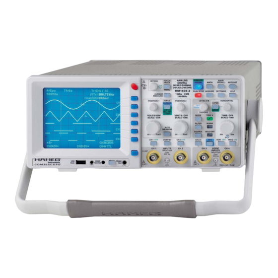
CombiScope HM1508-2
Hameg CombiScope HM1508-2 Oscilloscope Manuals
Manuals and User Guides for Hameg CombiScope HM1508-2 Oscilloscope. We have
2
Hameg CombiScope HM1508-2 Oscilloscope manuals available for free PDF download: Service Manual, Manual
Hameg CombiScope HM1508-2 Service Manual (103 pages)
Brand:
Hameg
| Category:
Measuring Instruments
| Size: 6 MB
Table of Contents
Performance Check Hm1508-2
28
R2031: 100 Hz Square Wave 5 MV/DIV CH
1
R2231: 100 Hz Square Wave 5 MV/DIV CH
2
A Test Instruments Required
3
C Software Adjustment Menu
3
D Checks
3
Table of Contents
28
B Performance Check 6) 2
3
CH2 2 MV/DIV: 100 Hz Square Wave
29
1: Attenuator Compensation
29
1: y Accuracy
29
CH2 5 MV/DIV: 100 Hz Square Wave
29
CH1 2 MV/DIV: 100 Hz Square Wave
29
CH1 5 MV/DIV: 100 Hz Square Wave
29
Trace Rotation Check
29
2: y Accuracy
31
ADD Accuracy (5 MV/DIV.)
32
2: Y-Amplifi er Overshoot (Analog/Digital)
32
1: 5 MV/DIV. Y-Amplifi er Bandwidth (Analog/Digital)
32
1: 1 MV/DIV. Y-Amplifi er Bandwidth (Analog/Digital)
33
1: 5 MV/DIV: XY Mode X Bandwidth (Analog/Digital)
33
1 Time Base A: Trigger Sensitivity (Internal Triggering)
33
1: Trigger Bandwidth (Internal Triggering)
34
Video Trigger Check
34
3 TTL Trigger Threshold Check
34
3 USER Defi Nable Trigger Threshold Check
34
Time Base A: Accuracy (Analog)
35
Time Base B: Accuracy (Analog)
35
Time Base A: Extern Trigger Bandwidth
35
Time Base A: Extern Trigger Sensitivity
35
Trigger Filter Check
35
Table of Contents
51
RV1001 +65 Volt Supply
54
RV1003 +12 Volt Supply
55
R9057: Readout Operating Point
56
Trace Rotation Check
56
R6013: CRT Minimum Intensity
57
RV1005 Focus Symmetry
57
Overall Correction and Save
58
R6024: Astigmatism Correction
58
READOUT FOCUS Correction
58
R2025: 100 Hz Square Wave 2 MV/DIV Adjustment
60
R2225: 100 Hz Square Wave 2 MV/DIV Adjustment
62
1, Input Capacitance Adaptation
63
C2023: CH 1, 10:1 Attenuator Compensation
64
1, 10:1 Attenuator Input Capacitance Adaptation
65
C2017
65
C2004: CH 1, 100:1 Attenuator Compensation
66
1, 100:1 Attenuator Input Capacitance Adaptation
67
C2006
67
2, Input Capacitance Adaptation
68
C2223: CH 2, 10:1 Attenuator Compensation
69
2, 10:1 Attenuator Input Capacitance Adaptation
70
C2217
70
C2204: CH 2, 100:1 Attenuator Compensation
71
2, 100:1 Attenuator Input Capacitance Adaptation
72
C2206
72
R9114: YP CH 1 Analog Gain
73
Readout Adjustment (Software Adjustment)
73
YP CH 1 Analog Gain (Software Adjustment)
74
YP CH 2 Analog Gain (Software Adjustment)
74
YP CH 1 Analog DC Offset (Software Adjustment)
75
YP CH 1 Analog Variable Balance (Software Adjustment)
75
YP CH 2 Analog DC Offset (Software Adjustment)
75
YP CH 2 Analog Variable Balance (Software Adjustment)
75
YP CH 1 Invert Symmetry (Software Adjustment)
76
YP CH 1 y Position (Software Adjustment)
76
YP CH 2 Invert Symmetry (Software Adjustment)
76
YP CH 2 y Position (Software Adjustment)
76
R4086: Horizontal X Gain
77
YP ADD y Position (Software Adjustment)
77
Horizontal XY Gain (Software Adjustment)
78
Horizontal XY Position (Software Adjustment)
78
Position (Software Adjustment)
78
Trigger Peak Peak CH 1 (Software Adjustment)
79
Trigger Peak Peak CH 2 (Software Adjustment)
79
Trigger Peak Peak External (Software Adjustment)
79
Trigger Point (Software Adjustment)
79
Acquire CH 1 Gain (Software Adjustment)
80
Acquire CH 1 Interlace (Software Adjustment)
80
Acquire CH 1 Position (Software Adjustment)
80
Trigger Counter (Software Adjustment)
80
Acquire CH 1 Interl. Pos. (Software Adjustment)
81
Acquire CH 2 Gain (Software Adjustment)
81
Acquire CH 2 Interlace (Software Adjustment)
81
Acquire CH 2 Position (Software Adjustment)
81
Acquire ADD Interl. Pos. (Software Adjustment)
82
Acquire ADD Position (Software Adjustment)
82
Acquire CH 2 Interl. Pos. (Software Adjustment)
82
Calibrator (Software Adjustment)
83
COMP. Tester (Software Adjustment)
83
R5107: COMP. Tester Trace Rotation
84
Timebase, Adjust 2 Timebase, a Timebase (Software Adjustment)
85
Timebase, Adjust 2 Timebase, B Timebase (Software Adjustment)
86
Saving Software Adjustments
87
C54 (C27), C63 (C31) Dot Join Adjustment
88
R4840: X-Mag. X10 Adjustment
89
C4809, C4810: X-Mag. X10 Trace Start Linearity
90
R9149: Y-Final Amplifi er Adjustment
91
R9118, C9045: Y-Final Amplifi er Adjustment
92
R9034 / C9001 and R9126 / C9037 Y-Final Amplifi er Adjustment
93
Amplifi er Bandwidth Check
95
C9009: HF Adjustment Y-Final Amplifi er
95
R161, C129: HF Adjustment CH 1 A/D Converter Driver
96
HF Adjustment CH 2 A/D Converter Driver Amplifi er
97
R162, C105
97
3, TTL Trigger Threshold Check
98
Video Trigger Check
98
3, USER Defi Nable Trigger Threshold Check
99
4, TTL Trigger Threshold Check
99
4, USER Defi Nable Trigger Threshold Check
100
Trigger Filter Check
100
External Trigger Check
101
Trigger Bandwidth Check
101
Input
102
Advertisement
Hameg CombiScope HM1508-2 Manual (54 pages)
150 MHz Mixed Signal
Brand:
Hameg
| Category:
Measuring Instruments
| Size: 1 MB
Table of Contents
General Information Regarding the CE Marking
4
Table of Contents
5
150 Mhz Mixed Signal Combiscope ® HM1508-2
7
Specifi Cations
7
Important Hints
8
List of Symbols Used
8
Positioning the Instrument
8
Safety
8
Environment of Use
8
Proper Operation
9
Cat I
9
Environmental Conditions
9
Warranty and Repair
9
Maintenance
9
Line Voltage
9
Description of the Controls
10
Basic Signal Measurement
12
Signals Which Can be Measured
12
Amplitude of Signals
12
Values of a Sine Wave Signal
12
DC and Ac Components of an Input Signal
13
Timing Relationships
13
Connection of Signals
13
First Time Operation and Initial Adjustments
14
Trace Rotation TR
14
Probe Adjustment and Use
14
1 Khz - Adjustment
14
Mhz Adjustment
15
Operating Modes of the Vertical Amplifi er
15
XY Operation
16
Phase Measurements with Lissajous Fi Gures
16
Measurement of Phase Differences in Dual Channel Yt Mode
16
Measurement of Amplitude Modulation
17
Triggering and Time Base
17
Automatic Peak Triggering (MODE Menu)
17
Normal Trigger Mode (See Menu MODE)
18
Slope Selection (Menu FILTER)
18
Trigger Coupling (Menu: FILTER)
18
Video (Tv Triggering)
18
Frame Sync Pulse Triggering
19
Line Sync Pulse Triggering
19
LINE Trigger
19
Alternate Trigger
19
External Triggering
19
Indication of Triggered Operation (TRIG'D LED)
19
Hold-Off Time Adjustment
19
Time Base B (2Nd Time Base). Delaying, Delayed Sweep. Analog Mode
20
Alternate Sweep
20
Autoset
21
Component Tester
21
Combiscope
23
DSO Operation
24
DSO Operating Modes
24
Memory Resolution
24
Memory Depth
25
Horizontal Resolution with X Magnifi er
25
Maximum Signal Frequency in DSO Mode
25
Display of Aliases
25
Vertical Amplifi er Operating Modes
25
Data Transfer
26
HO710: RS-232 Interface, Remote Control
26
Selection of Baud Rate
26
Data Transmission
26
Loading of New Fi Rmware
26
General Information Concerning MENU
27
Controls and Readout
28
Advertisement
Related Products
Hameg hm5510
Hameg HM5010
Hameg HM5011
Hameg HM5530
Hameg HM5014-2
Hameg HM 8027
Hameg HMS1000E
Hameg HMS1000
Hameg HMS1010
Hameg HMS3010
Hameg Categories
Test Equipment
Measuring Instruments
Power Supply
Multimeter
Recording Equipment
More Hameg Manuals
Login
Sign In
OR
Sign in with Facebook
Sign in with Google
Upload manual
Upload from disk
Upload from URL