Sign In
Upload
Manuals
Brands
Guildline Manuals
Measuring Instruments
6622T Series
Guildline 6622T Series Manuals
Manuals and User Guides for Guildline 6622T Series. We have
1
Guildline 6622T Series manual available for free PDF download: Operation Manual
Guildline 6622T Series Operation Manual (116 pages)
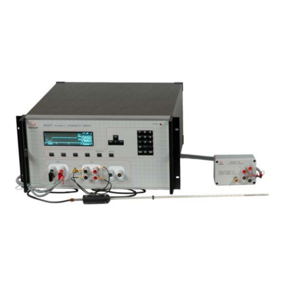
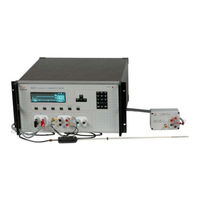
Automatic DCC Thermometry Bridges
Brand:
Guildline
| Category:
Measuring Instruments
| Size: 1 MB
Table of Contents
Table of Contents
3
Introduction
11
Scope
11
General Description
11
Overview
12
Principle of Operation
13
Figure 1-1 : Model 6622T Block Diagram
14
Low Ohm Measurement Mode
15
Normal Ohm Measurement Mode
15
Installation
17
Preliminaries
17
Unpacking
17
Power Voltage Selection
17
Fuse Replacement
18
Figure 2-1 : Line Voltage Selector
18
Table 2-1 : Fuse Ratings
18
Setup and Power on
19
Incoming Inspection
19
6622T Series Front Panel Display and Controls
21
Standard Resistor Input Terminals (Bench Model Only)
21
Figure 2-2 : 6622T Front View (Bench / Rack)
21
Resistor under Test Input Terminals (Bench Model Only)
22
Guard Terminal (Bench Model Only)
22
Circuit Common Terminal (Bench Model Only)
22
Power
22
Display
23
Numeric Keypad
23
Special Keys
23
Cursor Movement Keys
23
Function Keys
23
6622T Series Rear Panel Connectors and Controls
24
IEEE-488 Interface
24
Figure 2-3 : 6622T Rear View (Bench / Rack)
24
Line Input Connector
25
Standard Resistor Input Terminals (Rack Model Only)
25
Resistor under Test Input Terminals (Rack Model Only)
25
Guard Terminal (Rack Model Only)
25
Circuit Common Terminal (Rack Model Only)
25
Ground Terminal
26
Extender Connector
26
Quick Measurement Guide
27
Measurement Operation Guide
27
Figure 3-1 : Resistance Measurement Response Versus Test Sample
27
Normal Ohm Mode Resistance Measurement (All 6622T Models)
28
Figure 3-2 : Rear Panel Connections - Normal Ohm Mode
28
Table 3-1 : Recommended Normal Ohm Mode Test Setups
30
Low Ohm Mode Resistance Measurement (All 6622T Models)
31
Table 3-2 : 6623 Recommended Low Ohm Mode Test Setup
33
Table 3-3 : 6623A-300 Recommended Low Ohm Mode Test Setup
33
Figure 3-3 : Rear Panel Connections - Low Ohm Mode with 6623
34
Figure 3-4 : Rear Panel Connections - Low Ohm Mode with 6623A-300
35
Thermometry Measurement Mode
36
Table 3-4 : Recommended Temperature Measurement Test Setup
36
Figure 3-5 : Rear Panel Connections - Prt/Sprt
37
Bridgeworks Data Acquisition Software
38
Instrument Operation
39
Front Panel Operating Procedure
39
6622T Thermometry Measurement Bridge
39
Figure 4-1 : Menu Tree - Measure/Sofcal
40
Figure 4-2 : Menu Tree - Setup (Resistor)
41
Figure 4-3 : Menu Tree - Setup (Probe)
42
Figure 4-4 : Menu Tree - Measure-View
43
General Key/Display Operations
44
Base Menu
44
Basic Menu Operations
45
Menu Option-<MEASURE
45
Menu Option - <Any Other Menu but Measure
46
Base Edit/Select Menu - One Column of Data
47
Base Edit/Select Menu - Two Columns of Data
47
Operation of Select/Edit Data Menus
48
Function - <Scrn N-N
48
Function - <Edit
48
Function - <Ok
48
Title Screen
49
Main Menu
50
Measure> MENU Fn-1 (Main)
50
Measure> MENU Fn-1 (MAIN)
51
Measure> MENU Fn-1 (MAIN)
52
Setup> MENU Fn-1 (Setup_Main)
54
Profiles> MENU Fn-1 (Profiles MAIN)
54
View
55
Detail Graph
56
Detail
57
Window
57
Edit Ohms> MENU Fn-2 (Edit_Ohms MAIN)
58
Normal> MENU Fn-1 (Edit Ohms MAIN)
58
Low Ohms> MENU Fn-3 (Edit Ohms_Main)
59
Edit> MENU (Probe) Fn-2 (Edit MAIN)
61
IPTS 68> MENU Fn-1 (Edit MAIN)
61
ITS 90> MENU Fn-2 (Edit MAIN)
62
IEC 751> MENU Fn-3 (Edit MAIN)
64
Probe Set> MENU Fn-4 (Edit MAIN)
64
Sofcal> MENU Fn-3 (MAIN)
65
GPIB>MENU Fn-1 (Sofcal_Main)
67
Coef Set> MENU Fn-2 (Sofcal_Main)
67
Diagnostic> MENU Fn-3 (Sofcal_Main)
68
P.O.S.T.> MENU Fn-1 (Sofcal_Main)
71
Filter> MENU Fn-2 (Sofcal_Main)
72
Datum> MENU Fn-3 (Sofcal_Main)
72
Sys Time>Menu Fn-2 (Sofcal MAIN)
73
Extender>Menu Fn-3 (Sofcalmenu)
73
PASSWORD> MENU Fn-1 (Sofcal_Main)
78
Verification and Calibration
81
Resistance Ratio Accuracy Verification
81
Purpose
81
Equipment Required
81
Set up
82
Verification
82
Temperature Ratio Verification
84
Purpose
84
Equipment Required
84
Set up
85
Verification
85
Troubleshooting and Maintenance
87
Introduction
87
Error Messages
87
Table 6-1 : Model 6622T Error Messages
88
Model 6622T Setup Warnings
89
Bridge Coefficients
89
Quick Ratio Check
89
Purpose
90
Equipment Required
90
Set up
90
Check Procedure
91
Remote Control
93
Interfaces
93
Ieee-488 (Gpib) Interface
93
Controller
94
IEEE-488 Responses
94
Interconnecting Cable and IEEE-488 Connector
94
Table 7-1 : Factory Setting-Gpib
94
Typical System
95
Address and Talk/Listen Selection
96
IEEE-488 Electrical Interface
96
IEEE-488 Input Buffering
96
Table 7-2 : Ieee-488 Connector Pin Designations
97
IEEE-488 Output Buffering
98
IEEE-488 Deadlock
98
Table 7-3 : Model 6622T Ieee-488 Device Capabilities
98
Command Language
99
General Syntax for Commands
99
General Syntax for Numbers
99
Model 6622T Remote and Local Operation
99
Om6622T
99
Model 6622T Programming Command Summary
100
Appendices
115
GENERAL SPECIFICATIONS (Continued)
115
Table 8-1 : General Specifications (Continued)
115
Resistance Measurement Specification
116
Table 8-2 : Resistance Measurement Specification (All 6622T Models)
116
Advertisement
Advertisement
Related Products
Guildline 6675A
Guildline 6622A Series
Guildline 6622A-B
Guildline 6622A-XP
Guildline 6622A-XPS
Guildline 6622A-XR
Guildline 6622A-XPR
Guildline 6622A-HV
Guildline 6634A Resistance Standard
Guildline 6530 Series
Guildline Categories
Measuring Instruments
Extender
Industrial Electrical
Industrial Equipment
Decade Boxes
More Guildline Manuals
Login
Sign In
OR
Sign in with Facebook
Sign in with Google
Upload manual
Upload from disk
Upload from URL