Sign In
Upload
Manuals
Brands
GSi Manuals
Measuring Instruments
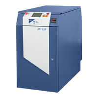
JK125P
GSi JK125P Manuals
Manuals and User Guides for GSi JK125P. We have
1
GSi JK125P manual available for free PDF download: User Manual
GSi JK125P User Manual (186 pages)
Brand:
GSi
| Category:
Measuring Instruments
| Size: 2 MB
Table of Contents
Table of Contents
7
General Information
17
Class of Laser
17
Intended Users
17
Documentation
17
Safety Paragraphs
17
Table of Definitions
18
After Sales Support
21
CE Mark Information
21
The JK300HP/JK300P/JK125P Series Laser
22
Main Assemblies
22
Control System and Local Controller
23
Machine Interface
23
Ancillaries
23
Technical Specification
24
Safety Interlocks
28
Customer Remote Interlocks
28
Shutter Interlocks (Beampath Interlocks)
28
Laser Power Delivery
29
Operating Parameters
31
Changing Parameters
31
Parameter Set Selection
33
Laser Outputs
33
Operating Guidelines
33
Processing Considerations
33
Fibre Optic Handling
34
Description
34
Unpacking Fibre Optic Cable
34
Fibre Installation
35
Minimum Bend Radii
35
Fibre Optic Termination
36
Fibre Routing
36
Fibre Removal
36
Safety
37
Laser Classification
37
Laser Radiation Hazards
39
Control Measures
39
Electrical Safety
41
Environmental Hazards
42
Fire
42
Fume
43
Compressed Gases
44
Solvents
44
Conditions of Use
45
Approved Materials
45
Approved Process
45
Approved Conditions
45
Due Authorisation
46
Safety Control System
47
Safety Category
47
Safety Compliance
47
Safety Labelling
47
Safety Features
50
Remote Interlock Connector
50
Workstation Interlock
51
Training
52
Personal Protective Equipment
52
Eye Protection
52
Manual Handling
52
Manual Handling Requirements
52
Pre-Installation
53
Location of Laser System
53
General Arrangement
54
Dimensions and Weight
54
Site Preparation
55
Electrical Supply Requirements
55
Cooling Water Supply
55
Gas Supply
57
Fume Control
57
Environmental Conditions
58
Temperature and Humidity
58
Degree of Protection Given by Enclosure
58
Electromagnetic Compatibility
58
Transportation
58
Electrical Connections
59
Connection Panel
59
PL601 - Customer Interlocks
59
PL602 - Workstation Interlocks
59
SK603 - Basic Machine (M/C) Interface
60
SK604 - Full M/C Interface - I/O Card 1 (Optional)
66
SK605 - Full M/C Interface - I/O Card 2 (Optional)
67
Fibre Route Planning
68
Installation Consumables
68
Pre-Installation Checks
69
Installation
71
Equipment Warranty
71
Installation Procedure
71
Installation Toolkit
72
Fibre Optic Handling
72
Installation Procedures
72
Certification
72
Commissioning
73
Disconnect Power Supply
73
Connector Removal
73
Disconnect External Water Supply
74
Drain Internal Cooling System
74
Fibre Removal
75
Re-Packaging
75
Laser Operation
77
Overview
77
Laser Start-Up
77
Laser Shut-Down
77
Emergency Shutdown
77
Keys
78
General
78
Control Keys
78
Navigation Keys
78
Function Keys
78
Value Keys
78
Editing Keys
78
Status Bar
79
Local Warnings
79
WELCOME Screen
79
Function
79
Entry
80
Exit
80
Laser Descr) {Laser Type} {S/W
80
MAIN Screen
80
Function
80
Entry/Exit
80
Operate
80
Setup
80
Alarm/Warnings
80
System
80
Entry/Exit
81
Status Bar
81
SETUP Screen
81
Function
81
Status Bar
82
MODIFY SHAPE Screens
82
Function
82
Entry/Exit
82
Title
82
Energy MONITOR Screen
83
Function
83
Entry/Exit
83
Status Bar
83
SYSTEM Screen
84
Function
84
Entry/Exit
84
ALARM / WARNINGS Screen
84
Display
84
Alarm/Warning
85
Alarm and Warning Handling
87
Alarm and Warning Display
87
Alarms for Generic Control System
87
System Level Alarms (Zone 1)
87
Alarm 1N01 : Communications Error
87
Alarm 1N02 : Serial Communications Fault
88
Alarm 1N03 : no Laser Type Configured
88
Alarm 1N04 : Laser Control Card Communication Fault
88
Alarm 1N05 : Pulse Generator Card Communication Fault
88
Alarm 1N06 : Interlock Module Communication Fault
88
Alarm 1N07 : Software Error
89
Alarm 1N08 : Safety Relay out Fault
89
Alarm 1N09 : Safety Relay in Fault
89
Alarm 1N10 : Safety Relay Not Detected
89
Alarm 1N11 : Emission Indicator Timeout
89
Alarm 1N12 : Laser Type Not Recognised by the Laser Control Network
90
Alarm 1N13 : LCC DSP Communications Fault
90
Alarm 1N14 : Unexpected Power down
90
Interlock Alarms (Zone 2)
90
Alarm 2N01 : Interlock Chain Input 1 Fault
90
Alarm 2N02 : Interlock Chain Input 2 Fault
91
Alarm 2N03 : Interlock Chain Input 3 Fault
91
Alarm 2N04 : Interlock Chain Input 4 Fault
91
Alarm 2N05 : Interlock Chain Input 5 Fault
91
Alarm 2N06 : Interlock Chain Input 6 Fault
92
Alarm 2N07 : Interlock Chain Input 7 Fault
92
Alarm 2N08 : Interlock Chain Input 8 Fault
92
Alarm 2N09 : Interlock Chain Input 9 Fault
92
Alarm 2N10 : Interlock Chain Input 10 Fault
93
Alarm 2N11 : Interlock Chain Input 11 Fault
93
Alarm 2N12 : Interlock Chain Input 12 Fault
93
Alarm 2N13 : Interlock Chain Input 13 Fault
93
Alarm 2N14 : Interlock Chain Input 14 Fault
94
Alarm 2N15 : Interlock Chain Input 15 Fault
94
Alarm 2N16 : Interlock Chain Input 16 Fault
95
Alarm 2N17 : Interlock Chain Input 17 Fault
95
Alarm 2N18 : Interlock Chain Input 18 Fault
96
Alarm 2N19 : Interlock Chain Input 19 Fault
96
Alarm 2N20 : Interlock Chain Input 20 Fault
97
Alarm 2N21 : Interlock Chain Input 21 Fault
97
Alarm 2N22 : Interlock Chain Input 22 Fault
97
Alarm 2N23 : Interlock Chain Input 23 Fault
97
Alarm 2N24 : Interlock Chain Input 24 Fault
98
Alarm 2N25 : Interlock Chain Input 25 Fault
98
Alarm 2N26 : Interlock Chain Input 26 Fault
98
Alarm 2N27 : Interlock Chain Input 27 Fault
98
Alarm 2N28 : Interlock Chain Input 28 Fault
98
Alarm 2N29 : Interlock Chain Input 29 Fault
99
Alarm 2N30 : Interlock Chain Input 30 Fault
99
Alarm 2N31 : Interlock Chain Input 31 Fault
99
Cooler Alarms (Zone 3)
99
Alarm 2N32 : Interlock Chain Input 32 Fault
99
Alarm 3N01 : Cooler Module Communication Fault
99
Alarm 3N02 : no Pump on Response
100
Alarm 3N03: Low Coolant Level
100
Alarm 3N04: over Temperature Switch
100
Alarm 3N05: Cooler Module Relay Fault
100
Alarm 3N06: Cooler Module Relay Overload Fault
101
Alarm 3N07: Low Temperature Fault
101
Alarm 3N08: High Temperature Fault
101
Alarm 3N09: very High Temperature Fault
101
Alarm 3N10: High Conductivity Fault
102
Alarm 3N11: Low Coolant Flow
102
Alarm 3N12: High Coolant Flow
102
Alarm 3N13: Temperature Sensor Fault
102
Alarm 3N14: Conductivity Sensor Fault
103
Power Supply Alarms (Zone 4)
103
Alarm 4N01 : Power Supply Module Communication Fault
103
Alarm 4N02 : Power Supply Software Error
103
Alarm 4N03 : Power Supply Negative 15 Volt Fault
103
Alarm 4N04 : Power Supply Fan Fault
103
Alarm 4N05 : Power Supply over Temperature
104
Alarm 4N06 : Power Supply Contactor in Fault
104
Alarm 4N07 : Power Supply Failed to Initialise
104
Alarm 4N08 : Power Supply Contactor in Timeout
104
Alarm 4N09 : Power Supply Failed to Simmer
104
Alarm 4N10 : Power Supply Failed to Simmer Timeout
105
Alarm 4N11 : Power Supply Simmer under Power Fault
105
Alarm 4N12 : Power Supply Simmer over Power Fault
105
Alarm 4N13 : Power Supply Failed to Enable
105
Alarm 4N14 : Power Supply Limit Fault
105
Alarm 4N15 : Power Supply IGBT Fault
106
Alarm 4N16 : Power Supply Earth Fault
106
Alarm 4N17 : Power Supply Input Voltage Loss
106
Alarm 4N18 : Power Supply Contactor out Fault
106
Alarm 4N19 : Power Supply Shutdown During Operation
106
Alarm 4N20 : Power Supply Contactor out Timeout
107
Shutter Alarms (Zone 5)
107
Alarm 4N21 : Power Supply Residual Voltage Fault
107
Alarm 5N01 : Shutter Communication Fault
107
Alarm 5N02 : Shutter Initialisation Failure
107
Alarm 5N03 : Shutter Configuration Failure
108
Alarm 5N05 : Shutter Emergency Stop Fault
108
Alarm 5N06 : Shutter Close Fault
108
Machine Interface Alarms (Zone 6)
108
Warning Number Allocation
109
System Level Warnings (Zone 1)
109
Warning 1N01 : Serial Link Buffer Overflow
109
Warning 1N02 : Laser Control Card Communications Overflow
109
Warning 1N03 : Incorrect Packet Data
109
Warning 1N04 : Data over Range
109
Warning 1N05 : Shutter Communications Timeout
110
Warning 1N06 : Sector over Range
110
Warning 1N07 : Operating Envelope over Range
110
Warning 1N08 : High Output Trip
110
Warning 1N09 : Low Output Trip
110
Warning 1N10 : Shot Limit Exceeded
110
Warning 1N11 : Shutter Multi Pulse External Trigger Timeout
110
Warning 1N12 : Shutter Multi Shot or Single Shot Not Allowed While Laser Is off
111
Cooler Warnings (Zone 3)
111
Warning 3N01 : Low Temperature
111
Warning 3N02 : High Temperature
111
Warning 3N03 : Low Flow
111
Warning 3N04 : High Flow
111
Warning 3N05 : High Conductivity
111
Power Supply Warnings (Zone 4)
111
Warning 4N01 : Disabled
111
Warning 4N02 : Dumping Current
112
Warning 4N03 : Dump Resistors Cooling
112
Shutter Warnings (Zone 5)
112
Warning 5N01 : Fibre Temperature
112
Warning 5N02 : Shutter Temperature
112
Warning 5N03 : FCMS
112
Warning 5N04 : External Work Chamber Doors
112
Warning 5N05 : Close
112
Warning 5N06 : Open
112
Warning 5N07 : Shutter Switch Feedback Error
113
Warning 5N08 : Energy Share Configuration Fail
113
Warning 5N09 : Datum Failure
113
Warning 5N10 : External Work Chamber Doors Open
113
Optimisation
115
Introduction
115
Initial Set-Up
115
Rear Mirror Tuning
116
Focus Head Setup
118
External Power Control (EPC) Set-Up
119
Set up Procedure
119
User Maintenance
121
Introduction
121
User Maintenance Tasks
122
General Inspection
123
Coolant Replenishment
124
Materials
124
Draining Procedure
124
Filling Procedure
126
Filter Replacement Procedure
128
Ioniser Replacement Procedure
130
Coolant Pump Replacement
132
Materials
132
Removal Procedure
132
Installation Procedure
134
Arc-Lamp Replacement
137
Materials
137
Replacement Procedure
138
Installation Procedure
140
PIPA Fibre Optic Cable Replacement
144
Materials
144
Removal Procedure
144
Installation Procedure
146
Fibre Output Termination Replacement Procedure
148
Alignment Procedure
150
Cover Slide Replacement Procedure
152
Materials
152
Removal Procedure
152
Cleaning and Installation Procedure
154
Focus Lens Cell Replacement Procedure
156
Materials
156
Replacement Procedure
156
Cleaning Procedure
158
Focus Lens Replacement Procedure
160
Materials
160
Removal Procedure
160
Installation Procedure
162
Surge Suppressor Replacement Procedure
164
Materials
164
Bulb Replacement Procedure
166
Materials
166
Bendlock Assembly
167
Assembly Instructions
167
Pointing Diode Replacement
168
Materials
168
Replacement Procedure
168
Alignment Procedure
170
Laser Processing
173
Overview
173
Welding with Pulsed Lasers
173
Pulse Energy
174
Peak Power
174
Pulse Frequency and Overlap
174
Welding in Continuous Wave Mode
175
Welding in Modulation Mode
175
Jigs and Fixtures
176
Shielding Gas
176
Fume and Spatter Control
177
Material Welding
178
Cutting in CW Mode
178
Cutting in Modulation Mode
179
Cutting Fixtures
179
Cutting Assist Gas
179
Inert Assist Gases
179
Cutting Different Materials
180
Process Preparation
180
Choice of Focused Spot Size
180
Part/Focus Position
180
Weld Shape, Cut Width and Joint Strength
180
Cover Slide Damage
181
Processing Access
181
Finding Focus
181
Welding
181
Cutting
183
Optimisation
184
Use of Ramp up and Ramp down
184
Record Keeping
184
Spares
185
Advertisement
Advertisement
Related Products
GSi JK300HP
GSi JK300P
GSi JS500
GSi 18
GSi ALLEGRO
GSi PRotek 3200 Series
GSi Protek A333
GSi Protek M733
GSi TYMPSTAR 1
GSi TYMPSTAR 2
GSi Categories
Farm Equipment
Industrial Equipment
Dryer
Construction Equipment
Heater
More GSi Manuals
Login
Sign In
OR
Sign in with Facebook
Sign in with Google
Upload manual
Upload from disk
Upload from URL