Sign In
Upload
Manuals
Brands
Groschopp Manuals
Controller
RBD-325-4/6-S
Groschopp RBD-325-4/6-S Manuals
Manuals and User Guides for Groschopp RBD-325-4/6-S. We have
1
Groschopp RBD-325-4/6-S manual available for free PDF download: Product Manual
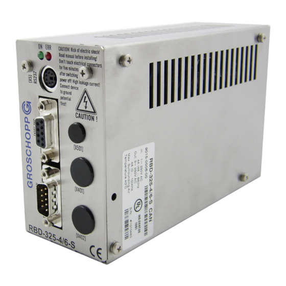
Groschopp RBD-325-4/6-S Product Manual (198 pages)
servo positioning controller
Brand:
Groschopp
| Category:
Controller
| Size: 4 MB
Table of Contents
Table of Contents
4
1 General
12
1.1 Symbols Used
12
Area of Applications and Intended Use
12
Type Description
12
1.2.2 Area of Application and Intended Use
13
Features of RBD-S
14
Specifications of RBD-S Servocommander TM
15
Basic Information
15
Hard- and Software-Conditions
16
Documentation
16
Delivery and Delivery Package
16
Table 2: Additional Parts
17
Table 3: Additional Parametering Program
17
2 Safety Notes for Electrical Drives and Controllers
19
2.1 General Notes
19
2.2 Danger Resulting from Use
20
2.3 Safety Notes
20
General Safety Notes
20
Safety Notes for Assembly and Maintenance
22
2.3.3 Protection against Contact with Electrical Parts
23
Protection against Electrical Shock by Means of Protective Extra-Low Voltage (PELV)
24
Protection against Dangerous Movement
24
2.3.6 Protection against Contact with Hot Parts
25
2.3.7 Protection During Handling and Assembly
25
3 First Commissioning of Drive
27
System Overview
27
Figure 1: Overview RBD 325-4/6-S
27
Connection of RBD-S Communication Interface
28
Installation and Start up of RBD-S Servocommander TM
28
Table 4: Overview Total System RBD 325-4/6-S
28
4 First Commissioning of Drive
29
First Commissioning
29
Parameter Settings at Delivery
29
Manual First Commissioning
29
Parameterization Across Motor Data File List
30
Basic Parameter of New Motors
31
Angle Encoder
31
Table 5: Parameter Encoder (Grey = Not Supported)
33
Motor Data
34
Power Stage
36
Current Controller
37
DC Bus Monitoring
38
Figure 2: Overshoot Current Controller
38
Motor Temperature Monitoring
39
Application Parameters
40
General Configuration
40
Adjustment of the Display Units
41
Table 6: Display Units
42
Specify Input Limits
43
Safety Parameter Selection
44
Adjustment Controller Enable Logic
45
Setting of the Limit Switch
45
Set up the Rotation Direction
46
Ready for Operation, Enable the End Stage
47
Manual "RBD-325-4/6-S" Version
47
Table 7: Error Reset Speed Controller
48
5 Current and Speed Controller
49
Functions Overview
49
Figure 3: Control Scheme of the Controller Cascade
50
Speed Control Command
51
Optimizing Speed Controller
51
Strategy to Optimization
52
Figure 4: Speed Controller - to Light
53
Figure 5: Speed Controller - to Hard
53
Figure 6: Speed Controller - Right Adjustment
53
Current Controller Optimization
54
Set Point over Set Point Selectors
54
Speed Controller Application
55
Torque Control Command
55
Settings Via RS232
56
Set Point Ramps
56
Current Controller with Torque Limitation
57
6 Position Application
58
Functions Overview
58
Figure 7: Positioning Control Block Diagram
58
Activate Commands
59
Positioning Adjusting and Optimizing
60
Optimizing the Positioning Controller
61
Figure 8: Optimised Positioncontroller
61
General Positioning Settings
62
Destination Parameters
63
Move to Destination
65
Figure 9: Time Optimum and Jerkfree Positioning
65
Settings of Digital Outputs
66
Homing Mode
66
Homing Movement
66
Figure 10: Homing with Negative Limit Switch and Zero Pulse
67
Figure 11: Homing with Positive Limit Switch and Zero Pulse
67
Figure 12: Homing on Negative Limit Switch
68
Figure 13: Homing on Positive Limit Switch
68
Figure 14: Homing Only with Zero Pulse
68
Figure 15: Homing with Negative Stop and Zero Pulse
69
Figure 16: Homing with Positive Stop and Zero Pulse
69
Figure 17: Homing with Negative Stop
69
Setting Homing Movement
70
Figure 18: Homing with Positive Stop
70
7 Course Program
73
Table 8: Course Program: Pin Configuration Digital Inputs (Standard)
73
Table 9: Course Program: Pin Configuration Digital Inputs (New I/O Lay Out)
74
Composing of Course Program
75
Table 10: Available Position Sets of Activated Course Program and Input weg = 0
75
Options of the Course Program
76
End of Program
77
Position Branch
77
Figure 19: Course Program - Position Branch
78
Figure 20: Timing Diagram Position Branch
78
Branch (Line)
79
Figure 21: Course Program - Branch Line
79
Figure 22: Timing Diagram Branch (Line)
80
Level Test
80
Course Program Debug
81
Figure 23: Course Program Level Test
81
Figure 24: Timing Diagram Level Test
81
8 Gear Synchronization over X10
83
Introduction
83
Incremental Encoder Emulation
83
Figure 25: Connection Incremental Encoder Emulation
83
Description of the Function and Application
84
Activating and Altitude
85
Synchronization over [X10]
85
Description the Function and Application
85
Figure 26: Synchronisation - Leveling Setpoints Speed- and Position Cotroller
86
Figure 27: Synchronisation - Minimum Times for a / B / N Signals
88
Figure 28: Synchronisieren - Minimum Times for CLK / dir Signals
88
Activating and Altitude
89
9 Function of In- and Outputs
92
Digital Inputs DIN0 to DIN9
92
Table 11: RBD-S Digital Inputs - Possible Combinations
92
Attitude of the Digital Inputs
93
Table 12: Digital Input - Layout
93
Extended Functions of Digital Inputs (Jogging & Teach)
94
Position Teaching
95
Table 13: Jogging & Learning: Layout of Digital Input
95
Figure 29: Learning a Destination
96
Digital Outputs DOUT0 to DOUT3
97
Settings of Digital Outputs
97
Settings of Messages for the Digital Outputs
98
Holding Brake DOUT3 (BRAKE)
100
Brake Functions
100
Analogue Inputs AIN0 and AIN1
101
Figure 30: Time Functions Holding Brake
101
Figure 31: Safety Zero
102
Analogue Output AMON
103
10 Communication Interfaces
104
Control of the CAN-Bus
104
Function Overview
104
Processing of CAN-Messages
104
Attitudes of the CAN Open Communications Parameters
105
Controlling over the Serial Interface
106
Functions Overview
106
Serial Communication Via RBD-S Servocommander TM
107
Settings Via RS232 Communication Parameters
107
Transfer Window
108
Communication Window Via RS232 Transfer
108
Controlling by Technologic Interface
109
11 Error Message/Error Management
110
Error Control by RBD-S
110
11.1.1 over Current and Short-Circuit Control
110
11.1.2 Monitoring DC-Bus Voltage
110
11.1.3 Monitoring Logic Supply
111
11.1.4 Monitoring of the Heat Sink Temperature
111
11.1.5 Monitoring of the Motor
111
11.1.6 Monitoring Course of Motion
111
11.1.7 Additional Internal Monitoring Functions
112
11.1.8 Operating Time Counter
112
Error Message Overview
112
Table 14: Error Overview
113
Error Signals on RBD-S
116
Error Window in RBD-S Servocommander
116
Error Management
117
12 Appendix
118
Working Description for RBD-S Servocommander TM
118
Standard Buttons
118
Numeric Input Field
118
Control Units
119
Representation of Settings and Actual Values
119
Table 15: Control Elements
119
Actual Window
120
Listings
121
Communication Across Communications Objects
121
Finishing the Program
121
Table 16: Listing Structure
121
Renew the Serial Communication
122
Table 17: Problem Solving of Serial Communication
123
Info-Window
124
Quick Access Via Symbol
125
Use of the Oscilloscope Functions
126
Oscilloscope Settings
126
Oscilloscope Window
128
Serial Communication Protocol
131
Table 18: Command Syntax Ok's
131
Table 19: Letter Description in the Command Syntax
131
Table 20: Command Syntax RS232
132
Table 21: Letter Description in the Command Syntax
132
Use of Communication Objects
133
Table 22: List of All Ok's
133
Basic Units
141
Table 23: List of Display Units
141
Bit Allocation Commandword / Controlword / Errorword
142
RS232-Command Word / Overview Important Orders
146
Table 24: List of RS232- Send Command (RS232-Command Word)
146
Apendix Possibilities Diplay Units
147
Settings of User Specified Display Units
147
Decimal Places
148
Direct Input Position-, Speed- and Acceleration Units
148
Course Program: Example
150
Example 1: Linear Connected Positions
150
Example 2: Linear Connected of Positions with Switching of a Digital Output
151
12.10 Timing Overview
152
Example 3: Settings and Checking of Digital In- and Outputs; Continuous Loop
152
Switching Sequence
153
Positioning / Destination Reached
154
Speed Message
154
Error Reset
155
Limit Switch
155
12.11 Parameter Set Administration
156
General
156
Figure 32: Online-Parametering
156
Load and Save Parameters
157
Print Parameter Settings
158
12.12 Offline Parameterization
160
Figure 33: Offline-Parametering
160
Table 25: Online-Offline-Activation
160
Loading Software into the RBD-S / Software Update
161
Loading Software
162
12.14 Technical Specifications
164
Site Conditions and Qualification
164
Dimensions and Weight
164
Power Data [X6], [X2A]
165
Motor Temperature Control [X2A]
165
Motor Phases [X6]
165
Resolver [X2A]
166
Analogue Hall Sensing [X2A]
166
Incremental Encoder Output [X10]
166
Incremental Encoder Input [X10]
167
Rs232 [X5]
167
CAN-Bus [X4]
167
Analogue In- and Output [X2B]
167
Digital In- and Output [X2B]
168
12.14.14 Warning and Status LED RBD-S
168
12.15 Mechanical Installation
169
Important Notes for Mounting
169
Front Side - Dimensions - Position Connectors
170
Figure 34: Front Side RBD 325-4/6S
170
Back Side - Position of the Connector
171
Table 26: Front Side RBD 325-4/6-S (Position of Connectors)
171
Table 27: Back Side RBD 325-4/6-S (Position of Connectors)
171
Figure 35: Back Side RBD 325-4/6S
172
Side View - Dimensions - Position of the Connectors When Using Small Mounting Plate
173
Smallest Mounting Distance
173
Figure 36: Side View RBD 325-4/6S
173
Figure 37: Smallest Mounting Distance
174
12.16 Connectors on the RBD-S
175
Pin Configuration: Analogue and Digital I/Os [X2B]
175
Table 28: Pin Configuration [X2B] - Send Command (Analogue / Digital)
175
Pin Configuration: Angle Encoder and Holding Brake [X2A]
176
Table 29: Pin Configuration [X2A] - Encoder Interface and Logic Supply
176
Pin Configuration: Motor and Power Supply [X6]
177
Table 30: Pin Configuration [X6] - Motor- and Power Supply
177
Pin Configuration: Internal Technologic Module Connection [X8]
178
Table 31: Connection of Connector [X8]
178
Pin Configuration: CAN-Bus [X4]
180
Optional: Connection: CAN-Bus In- and Output |X401, X402]
180
Table 32: Pin Configuration [X4] - CAN - Bus
180
Table 33: Connection of Connector [X401, X402]
180
Pin Configuration: PROFIBUS [X401, X402]
181
Pin Configuration: Ethercat [X401, X402]
181
Table 34: Connection of Connector [X401, X402]
181
Table 35: Connection of Connector [X401, X402]
181
Pin Configuration: Serial Parameterization Interface [X5]
182
Table 36: Pin Configuration [X5] - Serial Interface
182
Pin Configuration: Incremental Encoder In- and Output [X10]
183
Table 37: Pin Configuration [X10] - Incremental Encoder In- and Output
183
12.17 Electrical Installation of the RBD-S
184
Connecting to Supply [X6] and Motor [X6], [X2B]
184
Detail View - Connection of Motor with Resolver [X6], [X2A]
187
Table 38: Pin Configuration Motor Connector with Resolver
188
Detail View - Connection of Motor with Hallsensing System [X6], [X2A]
189
Table 39: Pin Configuration Motor Connector with Analogue Hall Sensing System
190
Connection of Analogue and Digital In- and Output [X2B]
191
Connection: CAN - Bus [X4]
192
Figure 45: CAN-Connection for RBD-S
192
12.18 Notes Concerning Safe and EMC-Compliant Installation
193
Definitions and Terminology
193
General Information Concerning EMC
194
Advertisement
Advertisement
Related Products
Groschopp Categories
Controller
Engine
More Groschopp Manuals
Login
Sign In
OR
Sign in with Facebook
Sign in with Google
Upload manual
Upload from disk
Upload from URL