Table of Contents
Advertisement
Product manual
RBD-325-4/6-S
Copyrights
2010 Groschopp BV Drives & More. All rights reserved.
The information and data in this document have been composed to the best of our knowledge.
However, deviations between the document and the product cannot be excluded entirely. For the
devices and the corresponding software in the version handed out to the customer, Groschopp BV
guarantees the contractual use in accordance with the user documentation. In the case of serious
deviations from the user documentation, Groschopp BV has the right and the obligation to repair,
unless it would involve an unreasonable effort. A possible liability does not include deficiencies caused
by deviations from the operating conditions intended for the device and described in the user
documentation.
Advertisement
Table of Contents

Summary of Contents for Groschopp RBD-325-4/6-S
- Page 1 However, deviations between the document and the product cannot be excluded entirely. For the devices and the corresponding software in the version handed out to the customer, Groschopp BV guarantees the contractual use in accordance with the user documentation. In the case of serious deviations from the user documentation, Groschopp BV has the right and the obligation to repair, unless it would involve an unreasonable effort.
- Page 2 Groschopp BV Drives & More reserves the right to modify, amend, or improve the document or the product without prior notification.
- Page 3 Page 3 Revision log Author: Groschopp BV, Drives & More Manual name: Manual„ RBD-325-4/6-S“ File name: Manual_RBD-325-4-6-S_2p0_UL File location: Handleidingen RBD-S Series No. Description Revisions-Index Date of changing’s Rev. 0.0 Release for distribution 01.02.2011 SR Manual“RBD-325-4/6-S“ Version 2.0.0...
-
Page 4: Table Of Contents
Specify input limits ....................43 Safety parameter selection ................. 44 Adjustment controller enable logic ..............45 Setting of the limit switch ..................45 Set up the rotation direction................46 4.10 Ready for operation, enable the end stage ............47 Manual “RBD-325-4/6-S“ Version 2.0.0... - Page 5 Digital outputs DOUT0 to DOUT3............... 97 9.3.1 Settings of digital outputs ...................97 9.3.2 Settings of messages for the digital outputs ............98 Holding brake DOUT3 (BRAKE) ............... 100 9.4.1 Brake functions ....................100 Analogue inputs AIN0 and AIN1 ............... 101 Manual“RBD-325-4/6-S“ Version 2.0.0...
- Page 6 RS232-command word / overview important orders ........146 12.8 Apendix possibilities diplay units ..............147 12.8.1 Settings of user specified display units ............147 12.8.2 Decimal places ....................148 12.8.3 Direct input position-, speed- and acceleration units ........148 12.9 Course program: Example ................150 Manual “RBD-325-4/6-S“ Version 2.0.0...
- Page 7 12.17.4 Connection of analogue and digital in- and output [X2B] .........191 12.17.5 Connection: CAN – Bus [X4] ................192 12.18 Notes concerning safe and EMC-compliant installation ........193 12.18.1 Definitions and terminology ................193 12.18.2 General information concerning EMC ..............194 Manual“RBD-325-4/6-S“ Version 2.0.0...
- Page 8 Page 8 12.18.3 EMC ranges: first and second environment .............194 12.18.4 Connection between RBD-S and Motor ............194 12.18.5 Connection between RBD-S and power- also logic - supply ......194 Manual “RBD-325-4/6-S“ Version 2.0.0...
- Page 9 Figure 31: Safety zero ..........................102 Figure 32: Online-Parametering ......................156 Figure 33: Offline-Parametering ......................160 Figure 34: Front side RBD 325-4/6S ....................170 Figure 35: Back side RBD 325-4/6S ....................172 Figure 36: Side view RBD 325-4/6S .....................173 Figure 37: Smallest mounting distance ....................174 Manual“RBD-325-4/6-S“ Version 2.0.0...
- Page 10 Table 20: Command syntax RS232 .....................132 Table 21: Letter description in the command syntax ................132 Table 22: List of all OK's ........................133 Table 23: List of display units .......................141 Table 24: List of RS232- Send command (RS232-command word) ............146 Manual “RBD-325-4/6-S“ Version 2.0.0...
- Page 11 Table 36: Pin configuration [X5] – serial interface ................182 Table 37: Pin configuration [X10] – Incremental encoder in- and output ..........183 Table 38: Pin configuration motor connector with resolver ..............188 Table 39: Pin configuration motor connector with analogue hall sensing system........190 Manual“RBD-325-4/6-S“ Version 2.0.0...
-
Page 12: General
The Servo positioning controller series RBD-S (Regulator for Brushless motors with permanent magnet rotor, Digital) are intelligent servo inverters with extensive parameterization options. Due to this flexibility, they can be adapted to numerous areas of application. Key type: Manual RBD-325-4/6-S“ Version 2.0.0... -
Page 13: 1.2.2 Area Of Application And Intended Use
In case of doubt, please contact your local distributor. The RBD-S may only be used in the environment described and with the technical data of the controller stated in the appendix in chapter 12.14. Manual “RBD-325-4/6-S“ Version 2.0.0... -
Page 14: Features Of Rbd-S
Integrated universal rotary encoder evaluation for the following encoder types: Resolvers ® Analogue Hall sensors (Groschopp Volksservo Mounting plate with double function - strain relief and screen connection of cable Compliance with current CE and EN standards with an additional external line filter. Other filters e.g. -
Page 15: Specifications Of Rbd-S Servocommander Tm
The software of the servo positioning controller RBD-S and the parameter software must be related to each other. In this way you can realise the best and latest modifications during parameterization. With this parameter software it is not possible to program other Groschopp devices! 1.3.2... -
Page 16: Hard- And Software-Conditions
The servo position controller RBD-S is within a CAN-Bus interface. Also available are devices with Profibus-Interface or with EtherCAT-Bus interface. Table 1: Basic device package options Servo position controller RBD-325-4/6-S Groschopp no. Basic with CAN-Bus interface RBD-S Can (Basic device) incl. -
Page 17: Table 2: Additional Parts
Page 17 Servo position controller RBD-325-4/6-S Profibus Groschopp no. Basic with Profibus-Bus interface RBD-S PB incl. mounting angle plate and screen cage clamp. Basic default settings for resolver motors. Servo position controller RBD-325-4/6-S Groschopp nr. EtherCAT RBD-S EC Basic with Ethercat-Bus interface incl. - Page 18 Page 18 Table 3: Additional parameter program RBD-S ServoCommander First delivery of RBD-S includes paper ® Windows -Parameter program manual for first commissioning eutsch/English/France/Dutch Manual RBD-325-4/6-S“ Version 2.0.0...
-
Page 19: Safety Notes For Electrical Drives And Controllers
Information In case of damage resulting from non-compliance with the safety notes in this manual Groschopp BV do not assume any liability If the documentation in the language at hand is not understood accurately, please contact and inform your supplier. -
Page 20: 2.2 Danger Resulting From Use
2.3 Safety notes 2.3.1 General safety notes The servo drive controller corresponds to IP20 class of protection as well as pollution level 1. Make sure that the environment corresponds to this class of protection and pollution level. Manual RBD-325-4/6-S“ Version 2.0.0... - Page 21 The general setup and safety regulations for work on power installations (e.g. DIN, VDE, EN, IEC or other national and international regulations) must be complied with. Non-compliance may result in death, personal injury or serious property damage. Manual “RBD-325-4/6-S“ Version 2.0.0...
-
Page 22: Safety Notes For Assembly And Maintenance
DC bus circuit is discharged, in the case of: Maintenance and repair work Cleaning Long machine shutdowns Prior to carrying out maintenance work make sure that the power supply has been turned off, locked and the DC bus circuit is discharged. Manual RBD-325-4/6-S“ Version 2.0.0... -
Page 23: 2.3.3 Protection Against Contact With Electrical Parts
Before switching on the device, install the appropriate covers and protections against accidental contact. Rack-mounted devices must be protected against accidental contact by means of a housing, e.g. a switch cabinet. The regulations VGB4 must be complied with! Manual “RBD-325-4/6-S“ Version 2.0.0... -
Page 24: Protection Against Electrical Shock By Means Of Protective Extra-Low Voltage (Pelv)
2.3.5 Protection against dangerous movements Dangerous movements can be caused by faulty control of connected motors, for different reasons: Improper or faulty wiring or cabling Error in handling of components Error in sensor or transducer Defective or non-EMC-compliant components Manual RBD-325-4/6-S“ Version 2.0.0... -
Page 25: 2.3.6 Protection Against Contact With Hot Parts
2.3.7 Protection during handling and assembly Handling and assembly of certain parts and components in an unsuitable manner may under adverse conditions cause injuries. DANGER! Risk of injury due to improper handling! Manual “RBD-325-4/6-S“ Version 2.0.0... - Page 26 Use suitable tools only. If specified, use special tools. Use lifting devices and tools appropriately. If necessary, use suitable protective equipment (e.g. goggles, protective footwear, and protective gloves). Do not stand underneath hanging loads. Remove leaking liquids from the floor immediately to prevent slipping. Manual RBD-325-4/6-S“ Version 2.0.0...
-
Page 27: First Commissioning Of Drive
I/O’s or field bus. The components necessary for using the RBD-S are shown in the figure and declared in Table 4 on the next side. Figure 1: Overview RBD 325-4/6-S Manual “RBD-325-4/6-S“ Version 2.0.0... -
Page 28: Connection Of Rbd-S Communication Interface
5. Follow the descriptions of the installation program. The installation program makes a new file with the name „Groschopp“. In this file you can find the program „RBD-S [Version no.] under „RBD-S ServoCommander“. With this opened you can start the parameter program. -
Page 29: First Commissioning Of Drive
3. Options/ input limits... 4. Parameter/device parameter/motor data... motor identification across a motor list 5. Parameter/device parameter/angle encoder adjustments... 6. Parameter/safety parameters... 7. Parameter/controller parameters/current controller... 8. Parameter/controller parameters/speed controller... 9. Parameter/controller parameter/position controller... 10. Parameter/device parameters/temperature monitoring... Manual “RBD-325-4/6-S“ Version 2.0.0... -
Page 30: Parameterization Across Motor Data File List
It is an additional tool for users. On the CD-Rom you will find only the DCO files of every existing Groschopp motor type. If there is no DCO applicable in the list please contact your supplier. We can make and deliver it (see quick manual in the package). -
Page 31: Basic Parameter Of New Motors
The function can be adjusted via the following paths: Parameter/device parameter/motor data: Button "Automatic offset detection" Parameter/device parameter/angle encoder adjustment: Button " Automatic offset detection " Manual “RBD-325-4/6-S“ Version 2.0.0... - Page 32 Activate the angle encoder adjustment with Automatic offset detection. The following window appears: Caution! During this identification the axis will rotate automatically for a few seconds. Manual RBD-325-4/6-S“ Version 2.0.0...
-
Page 33: Table 5: Parameter Encoder (Grey = Not Supported)
We advise you to contact your supplier to make the right adjustments, Table 5: Parameter angle encoder (blank = not implemented) Resolver Analogue hall sensor Offset angle encoder Phase line Pulses Zero impulse (yes/no) Manual “RBD-325-4/6-S“ Version 2.0.0... -
Page 34: Motor Data
The best compromise of smoothly rotating and constant accuracy gives the best result if the P-component in speed controller of EMC- is also selected. 4.3.2 Motor data These points must be followed if the motor is not shown in the list. Manual RBD-325-4/6-S“ Version 2.0.0... - Page 35 To a Speed set point. Nenn − × × Nenn Over the selection advanced parameter you can input the calculated motor-EMK and other parameter settings.. Manual “RBD-325-4/6-S“ Version 2.0.0...
-
Page 36: Power Stage
For the controller regulation behaviour the clock frequency has little influence. The basic clock frequency of the power stage is therefore fixed at 10 kHz. The RBD-S controller has a fixed clock frequency of 10 kHz. Manual RBD-325-4/6-S“ Version 2.0.0... -
Page 37: Current Controller
Put in the correct parameters. When you are not sure please use the general uncritical values. Caution! Wrong values can give heavy ripples or short over current and can damage the motor. With the servo position controller you can activate the over current protection! Manual “RBD-325-4/6-S“ Version 2.0.0... -
Page 38: Dc Bus Monitoring
This safety function is for this reason not adjustable.. Too low DC bus voltage can cause an error and therefore this is adjustable. The DC bus window can be activated with parameter/device parameter/DC bus monitoring. Manual RBD-325-4/6-S“ Version 2.0.0... -
Page 39: Motor Temperature Monitoring
In field error management you can select, how the servo position controller reacts to an under voltage (see chapter 11.5 Error management). 4.3.6 Motor temperature monitoring If your motor has a temperature sensor, you can adjust it by parameter/device parameter/temperature monitoring: Manual “RBD-325-4/6-S“ Version 2.0.0... -
Page 40: Application Parameters
KTY 81/82-210/220/250 KTY 81/82-110/120/150 KTY 83-110/120/150 KTY 84-130/150 Application parameters 4.4.1 General configuration The possible attitudes are dependant on the general configuration, which can be input via parameter/application parameter/general configuration. The following application windows will be shown: Manual RBD-325-4/6-S“ Version 2.0.0... -
Page 41: Adjustment Of The Display Units
Every access over RS232-interface will be done with these basic units.. The user has the possibilities to use the following physical units: Position / speed Speed Acceleration Torque (in Nm or A) Manual “RBD-325-4/6-S“ Version 2.0.0... -
Page 42: Table 6: Display Units
For linear axle and not symmetrical distance, speed and acceleration units (e.g. inch, inch/min). For rotary gears with special distance, speed and acceleration units. Direct input Free input of distance, speed and acceleration units. Only for experienced users! Manual RBD-325-4/6-S“ Version 2.0.0... -
Page 43: Specify Input Limits
The input limits adapt automatically to the adjusted physical units, to allow you to control these. Click for this on the button Yes Specification of input limits Via Options/input limits the following menu is displayed: Manual “RBD-325-4/6-S“ Version 2.0.0... -
Page 44: Safety Parameter Selection
Cannot make a controlled stop of the gear by disconnecting the enable. (E.g. due to an error parameter setting), after this time the end stage will be shut down, the motor runs down, when the motor is not stopped on zero speed.. Manual RBD-325-4/6-S“ Version 2.0.0... -
Page 45: Adjustment Controller Enable Logic
For a controller enable DIN9 must be connected and also a command over CAN-Bus must be sent. Setting of the limit switch The servo position controller supports limit switches with normally open or normally closed contacts. Manual “RBD-325-4/6-S“ Version 2.0.0... -
Page 46: Set Up The Rotation Direction
Here it is possible to get a movement direction according to the angle count, the right sign of speed and current. Danger! By activating this option, the gear rotates with the same settings in counter clockwise! Manual RBD-325-4/6-S“ Version 2.0.0... -
Page 47: Ready For Operation, Enable The End Stage
In order to be moveable the engine speed adjusted, they must stop the still following points 1) Activate the speed control (see chapter 5.2 Speed control ). 2) Set the controller enable logic to “digital input (DIN9) “ only. (see chapter 4.7 Adjustment of controller enable logic). Manual “RBD-325-4/6-S“ Version 2.0.0... -
Page 48: Table 7: Error Reset Speed Controller
Read chapter Fout! Verwijzingsbron niet gevonden. Set point over set shown as „0“. point selectorsfor more information. Pay attention to the connection of the motor phases, they can vary with supplier of servo motor. You may have to change the phases U and W. Manual RBD-325-4/6-S“ Version 2.0.0... -
Page 49: Current And Speed Controller
In speed controller command we work with an offset speed value. The servo position controller RBD-S calculates the encoder resolution to an actual speed value n_act.. To realize the offset speed value the current offset i_off will be calculated. Manual “RBD-325-4/6-S“ Version 2.0.0... -
Page 50: Figure 3: Control Scheme Of The Controller Cascade
Page 50 Figure 3: Block diagram controller cascade Manual RBD-325-4/6-S“ Version 2.0.0... -
Page 51: Speed Control Command
The overshoot of the falling oscillation of the actual value may be a little under the set point value so it can return on the set point value. These adjustments are available for Manual “RBD-325-4/6-S“ Version 2.0.0... -
Page 52: Strategy To Optimization
Time base: 5 ms / div; delay = -5 ms Trigger: Source = speed set point; level = 50 rpm; mode = normal, rising trigger edge Disconnect ramps in set point selectors and put in maximum acceleration time. Manual RBD-325-4/6-S“ Version 2.0.0... -
Page 53: Figure 4: Speed Controller - To Light
Figure 5: speed controller too hard Remedy: Decrease the gain by 2 to 3 points of tenth/ then reduce the time constant by 1 to 2 ms Case 3: speed controller set correctly Figure 6: speed controller – set correctly Manual “RBD-325-4/6-S“ Version 2.0.0... -
Page 54: Current Controller Optimization
Fixed value RS232 Fixed value CAN Position controller (in command mode speed controller) Speed controller (in command mode torque control) If there is no source of desired value activated (inactive), then the set point is zero.. Manual RBD-325-4/6-S“ Version 2.0.0... -
Page 55: Speed Controller Application
In both situations the set point ramp generator is disconnected so that the torque limitation can be activated. Analogue input is activated but no line is visible, then the digital inputs are activated (see chapter 9.1.1 Attitude of the digital inputs) Manual “RBD-325-4/6-S“ Version 2.0.0... -
Page 56: Settings Via Rs232
The set point ramp generator can be activated and deactivated with the switch The menu for adjustment of the ramps can be set with set point selector menu over symbol or by Operating modus/Ramps. The following window shows: Manual RBD-325-4/6-S“ Version 2.0.0... -
Page 57: Current Controller With Torque Limitation
The input of torque offset can be done by torque limitation • The speed offset will be made by a separate offset input, so that if a „Rev up“ of the • missing load occurs, the speed produced is not a dangerous value. Manual “RBD-325-4/6-S“ Version 2.0.0... -
Page 58: Position Application
The positioning movements have many possible signals, which are be necessary when using • external controllers/PLC, e.g. target reached message and a following error. Figure 7: Positioning control block diagram Manual RBD-325-4/6-S“ Version 2.0.0... -
Page 59: Activate Commands
For the homing movement, or if positioning over CAN (DS402) is desired the appropriate position Targets come direct from the trajectory generator. Activate commands For adjusting the homing and positioning application:- You must configure the commands windows as follows: Manual “RBD-325-4/6-S“ Version 2.0.0... -
Page 60: Positioning Adjusting And Optimizing
Parameterization of a following error, also a message delay. If the deviation between offset- and actual value is bigger than the adjusted limit, a message or an error will be shown. Also the reaction type can be selected in the error management. Manual RBD-325-4/6-S“ Version 2.0.0... -
Page 61: Optimizing The Positioning Controller
Optimizing: Speed and rotor positioning by stop read out. When the start oscillation is too long the gain must be increased. When the speed starts to oscillate the gain must be reduced. Figure 8: Optimize positioning controller Consider by overshoot by inactive acceleration and braking time is caused. Manual “RBD-325-4/6-S“ Version 2.0.0... -
Page 62: General Positioning Settings
For changing the function 64 positions to 16 positions or opposite the RBD-S must be organized with the internal file structure internal. In this situation the actual settings will be lost. All position settings will be changed to the factory settings. After switching the destination parameters must be newly adjusted. Manual RBD-325-4/6-S“ Version 2.0.0... -
Page 63: Destination Parameters
The option relative obtains difference results, dependent on how the field Start during positioning is parameterized (see under). If the combination relative/wait for end is selected, the new position refers to the destination. Via the combination relative/interrupt actual positioning the new destination will be calculated from the actual offset positioning. Manual “RBD-325-4/6-S“ Version 2.0.0... - Page 64 In the field jerkfree positioning you can set up a filter time. Here the acceleration time will be tailored so that a jerkfree acceleration is created. Both figures show the speed profiles with and without jerkfree positioning. Manual RBD-325-4/6-S“ Version 2.0.0...
-
Page 65: Move To Destination
In addition you have the possibility to start a position by clicking the button GO! with the actual position Fout! Verwijzingsbron niet gevonden.). Manual “RBD-325-4/6-S“ Version 2.0.0... -
Page 66: Settings Of Digital Outputs
The numbers correspond also with the CAN open DSP402 fixed numbers of the homing mode. How to activate and parameterize the homing mode is described in chapter 6.8.2 Setting homing movement. Manual RBD-325-4/6-S“ Version 2.0.0... -
Page 67: Figure 10: Homing With Negative Limit Switch And Zero Pulse
Figure 12 by the rising edge. After that in crawl speed it searches for the end switch in the other direction. The zero position comes from falling edge from the negative limit switch. Manual “RBD-325-4/6-S“ Version 2.0.0... -
Page 68: Figure 12: Homing On Negative Limit Switch
For a movement to the zero position the option „Go to zero position after homing run “must be activated. An additional offset of the zero position can be put in the field „offset start position“. Manual RBD-325-4/6-S“ Version 2.0.0... -
Page 69: Figure 15: Homing With Negative Stop And Zero Pulse
With this method the gear moves in the positive direction until it reaches the mechanical stop. The servo positioning controller needs a minimum 1 second to recognize the mechanical stop. The stop must be dimensioned as the maximum current to avoid damage. The zero position comes direct from the stop. Manual “RBD-325-4/6-S“ Version 2.0.0... -
Page 70: Setting Homing Movement
Via the button Positioning settings in the menu it is possible to input the general settings (e.g. position limits). See chapter 6.4 Fout! Verwijzingsbron niet gevonden.. The button GO! can be selected to start the homing run. Manual RBD-325-4/6-S“ Version 2.0.0... - Page 71 (e.g. position limits). See chapter 6.4 General positioning settings If the option homing run at controller enable is activated, the homing runs starts automatically, when the enable is recognized. Manual “RBD-325-4/6-S“ Version 2.0.0...
- Page 72 Here are the settings for speed and acceleration for the following items: Search: Move the gear to the destination (limit switch, stop) Crawl: Running reversal (with reduced speed) to recognise the trigger point Running: Optional movement to the zero point (Basic point) of the application Manual RBD-325-4/6-S“ Version 2.0.0...
-
Page 73: Course Program
Signal sensitive inputs must be activated for a minimum 100µs. The digital inputs used for start and selecting a destination will be, by activated course program, as follows: Table 8: Course program: connection diagram of digital inputs (default) Manual “RBD-325-4/6-S“ Version 2.0.0... -
Page 74: Table 9: Course Program: Pin Configuration Digital Inputs (New I/O Lay Out)
The new I/O-connection shown in table 9 makes it possible to use a better function of the course program in combination with the double signals DIN2 / DOUT1 and DIN3 / DOUT2 from connector X1. It can be activated by the commands window (see Chapter. 6.2). Manual RBD-325-4/6-S“ Version 2.0.0... -
Page 75: Composing Of Course Program
When you select the button Edit line or a course program number a new window opens to allow composition of the settings in this course program number. The basic course program orders are Position branch (and linear following position) Branch line Level test (and absolute program jump) End of program Manual “RBD-325-4/6-S“ Version 2.0.0... -
Page 76: Options Of The Course Program
The branch line will not be implemented, the program stays in the actual program target The level test via signals NEXT1 and NEXT2 will also start again, after the stop signal is activated. The output signals DOUT1 and DOUT2 have no influence on the stop signal. Manual RBD-325-4/6-S“ Version 2.0.0... -
Page 77: End Of Program
If Evaluate Stop-Signal is activated, the running position can be interrupted. 7.1.3 Position branch Depending on NEXT1 and NEXT2 you can run to two separate positions. The course program runs in order of its order option selection. Manual “RBD-325-4/6-S“ Version 2.0.0... -
Page 78: Figure 19: Course Program - Position Branch
" is sent. Only the edges will be evaluated, which will be detected by the start of the program movement. When signal "Target reached" is set, without recognizing rising edge of NEXT1/2, the program stays in program step 11 until detecting edge of NEXT1/2. Figure 20: Time diagram position branch Manual RBD-325-4/6-S“ Version 2.0.0... -
Page 79: Branch (Line)
Again one expects that NEXT1/2 –signal will be active, before the positioning will be stopped. The evaluation will be started, and the selected course program target (next line 1 or 2, depending on which of NEXT1 or NEXT2 is selected first) will be started and finished. Manual “RBD-325-4/6-S“ Version 2.0.0... -
Page 80: Level Test
Page 80 Figure 22: Time diagram branch line 7.1.5 Level test Depending on the level test of NEXT1 the program runs to different targets. Manual RBD-325-4/6-S“ Version 2.0.0... -
Page 81: Course Program Debug
DOUT1 / DOUT2: shows the actual situation of the digital outputs of DOUT1 & 2. Line: shows the line, where the course program is at the moment. Additionally the actual line turns blue in the register table. Manual “RBD-325-4/6-S“ Version 2.0.0... - Page 82 Page 82 Position: shows the last reached position. Manual RBD-325-4/6-S“ Version 2.0.0...
-
Page 83: Gear Synchronization Over X10
Depending on the function the slave turns with synchronous rotation or a synchronous angle with the master. The configuration of the RBD-S to function as a slave is described in the next chapter Fout! Verwijzingsbron niet gevonden. Fout! Verwijzingsbron niet gevonden.. Manual “RBD-325-4/6-S“ Version 2.0.0... -
Page 84: Description Of The Function And Application
1 k Ω to 0 V. Then the maximum signal frequency of the level signals f = 50 kHz. max,A,B DOUT1 == Level signal A DOUT2 == Level signal B Manual RBD-325-4/6-S“ Version 2.0.0... -
Page 85: Activating And Altitude
The RBD-S can also be realized as a slave in a master-slave application. It supports these modes of operation: Rotation synchronous movement calculated from the synchronization offset. The RBD-S is selected in modes of operation speed control + synchronization. Manual “RBD-325-4/6-S“ Version 2.0.0... -
Page 86: Figure 26: Synchronisation - Leveling Setpoints Speed- And Position Cotroller
The determined angle first one differentiated, enclosed will the electrical gear with spitted parameterized numerator and denominator calculated. The on this way determined angle difference will be changed to the actual position offset of the synchronization, x_sync, integrated (Integrator). In Manual RBD-325-4/6-S“ Version 2.0.0... - Page 87 Adjust the level of the connected encoder on 1024 Adjust the electrical gear on N = 1024 and D = 360 Now the RBD-S uses each motor rotation of the reference encoder with 360 levels for each motor rotation. Manual “RBD-325-4/6-S“ Version 2.0.0...
-
Page 88: Figure 27: Synchronisation - Minimum Times For A / B / N Signals
= 250 kHz. This value is only valid for an „ideal “increment encoder. In practice, you get phase errors between the A and B level signals of the increment encoder. We advise a from there the enterprise f < 100 kHz. Manual RBD-325-4/6-S“ Version 2.0.0... -
Page 89: Activating And Altitude
This combination realizes a position synchronous application. A position plan can be overlaid. One touch on "..."-button by "synchronization" opens the window "incremental encoder simulation/synchronization" (see below). Alternatively it is possible to adjust these parameters via register Operation mode/Incremental encoder simulation – synchronization. Manual “RBD-325-4/6-S“ Version 2.0.0... - Page 90 CLK/DIR –Signals are suitable for the connection of the RBD-S to a step motor controller. The synchronous motor on the RBD-S behaves like a stepper motor. An advantage of this function is in overload situation except steppes o fall do not known. Manual RBD-325-4/6-S“ Version 2.0.0...
- Page 91 Master stationary after reference movement Controller enable slave, slave homing Slave stationary after reference movement Offset release master / master started The slave follows the master Manual “RBD-325-4/6-S“ Version 2.0.0...
-
Page 92: Function Of In- And Outputs
DIN0 DIN1 DIN2 DIN3 DIN4 DIN5 DIN6 DIN7 DIN8 DIN9 Analogue input active Incremental encoder emulation active (24 V-output) Analogue monitor active Digital outputs 1 & 2 active An overview of available digital inputs and the actual activated situation are shown on menu Display/digital inputs: Manual RBD-325-4/6-S“ Version 2.0.0... -
Page 93: Attitude Of The Digital Inputs
This functionality of DIN0 – DIN5 can only be used if the analogue inputs AIN0 and AIN1 are activated as digital inputs. When the incremental encoder emulation is active, DIN2 & DIN3 are not available as digital inputs. Manual “RBD-325-4/6-S“ Version 2.0.0... -
Page 94: Extended Functions Of Digital Inputs (Jogging & Teach)
The digital inputs used for starting and selecting positions, if activated, can be used in the following range: Manual RBD-325-4/6-S“ Version 2.0.0... -
Page 95: Position Teaching
(6) With the falling edge DIN 6 the actual position will be taken to the selected position. (7) The digital inputs will be ignored for a specified time, before they apply again. This time can be set in the window destination parameters under destination jogging & teaching. Manual “RBD-325-4/6-S“ Version 2.0.0... -
Page 96: Figure 29: Learning A Destination
>= 5 ms set pos >= 1,6 ms hold >= 200 ms (Parameter adjustable) ignore Attention! After expiration of time t the digital inputs return to their functionality as used for the ignore teaching modes. Manual RBD-325-4/6-S“ Version 2.0.0... -
Page 97: Digital Outputs Dout0 To Dout3
Remaining distance message Target reached Homing mode complete Course program Declared speed achieved With some selections a 3 dotted button appears behind the selection. When you push this button, an appropriate window opens to adjust the additional values. Manual “RBD-325-4/6-S“ Version 2.0.0... -
Page 98: Settings Of Messages For The Digital Outputs
Register card: Distention Angle/distance: Tolerance window, of the message „target reached “ is given. Message delay: Time delay, where the actual position must be in the range, before the message „target reached “ is given. Manual RBD-325-4/6-S“ Version 2.0.0... - Page 99 Page 99 Register card: Motor speed message Declared speed: Speed, of the message „Declared speed“ will given Message window: Tolerance window, where the actual speed must be in the range, before the message „declared speed“ is given. Manual “RBD-325-4/6-S“ Version 2.0.0...
-
Page 100: Holding Brake Dout3 (Brake)
. During this time the gear stays in this actual position, to the point of energizing the holding brake (brake on). After this time delay the enable will disconnect. In both situations the mechanical wear of the holding brake will be minimized. Manual RBD-325-4/6-S“ Version 2.0.0... -
Page 101: Analogue Inputs Ain0 And Ain1
12 Bit. These inputs can be flexibly used for the offset of rotation speed and torque set points. Via Parameter/I/Os/Analogue inputs or the „...“ Button with activated analogue inputs menu for the offset selectors can be found in the following menu: Manual “RBD-325-4/6-S“ Version 2.0.0... -
Page 102: Figure 31: Safety Zero
„Hole“ in the controlled system – see Figure 31. This is realized in the processing as an instable controller system. In this menu there are two register cards for both analogue inputs, so you have the possibility of scaling every register card. Manual RBD-325-4/6-S“ Version 2.0.0... -
Page 103: Analogue Output Amon
V, to this limits reduced. By a not activated box exceeds the +10V- values as voltage from 0V represented, and turned around. The option freely selectable communication objects is reserved for special applications. It is possible to use internal variables of the controller for other analysis. Manual “RBD-325-4/6-S“ Version 2.0.0... -
Page 104: Communication Interfaces
The PLC may not send more frequently than 4ms, otherwise the situation can be that the RBD-S • doesn’t register a PDO or process. This can be shown, for example, in a jumping in the controlling or a jerking of the motor. Manual RBD-325-4/6-S“ Version 2.0.0... -
Page 105: Attitudes Of The Can Open Communications Parameters
RESET of the servo positioning controller RBD-S. So it is possible, with easy connections of the 24V to the digital inputs, to use 16 different device numbers. To use this function, you must have parameterized the digital inputs (see chapter 9.1.1 Manual “RBD-325-4/6-S“ Version 2.0.0... -
Page 106: Controlling Over The Serial Interface
. In chapter 12.7 Use of communication objects there is a list of all supported communication objects. The controller internal value of a parameter can deviate slightly from the adjusted value of the servo position controller used internal other unit displays and standardizations as the communication objects. Manual RBD-325-4/6-S“ Version 2.0.0... -
Page 107: Serial Communication Via Rbd-S Servocommander Tm
This Baud rate is valid for "normal" online communication with the servo position controller. For the Software-Download you use a special Baud rate selection. In menu Option/Communication/Interface you can select the interface (COM-Port) and over the parameter program it will try to communicate with the servo position controller: Manual “RBD-325-4/6-S“ Version 2.0.0... -
Page 108: Transfer Window
Communication window via RS232 transfer The selection via menu Option/Communication/Display communication window (RS232) opens a window where you can see the communication over the serial interface. These are mainly for debugging cases, for ‘Normal users’ it isn’t of interest. Manual RBD-325-4/6-S“ Version 2.0.0... -
Page 109: Controlling By Technologic Interface
The servo position controller RBD-S has an additional technological interface which can be used for synchronous serial interface e.g. Profibus- or Ethercat communication and Client specified modules. So it is possible to develop and deliver client specified technological modules. This is only of interest for quantities. Please contact your supplier. Manual “RBD-325-4/6-S“ Version 2.0.0... -
Page 110: Error Message/Error Management
Under voltage monitoring: The DC-bus voltage will be monitored on the under border (see chapter Fout! Verwijzingsbron niet gevonden. Fout! Verwijzingsbron niet gevonden.). The reaction on this error is for applications with „learning movement “of the DC-bus voltage or an application with reduced DC-bus voltage to parameterize. Manual RBD-325-4/6-S“ Version 2.0.0... -
Page 111: 11.1.3 Monitoring Logic Supply
Positioning range: A running position will be monitored on an adjustable position range. Limit switch: If both limit switches are activated then an error occurs. Course program: The course program monitored during processing on wrong orders. Manual “RBD-325-4/6-S“ Version 2.0.0... -
Page 112: 11.1.7 Additional Internal Monitoring Functions
Show: The disturbance will be shown, nothing further happens. Do not show: The disturbance will be ignored. The column error shows a red blinking code ERR-LED on the front of the RBD-S Manual RBD-325-4/6-S“ Version 2.0.0... -
Page 113: Table 14: Error Overview
Short circuit in cable between two phases or between phase and screen? Test isolation of motor phase connections? Over current DC-bus / power Defective RBD-S (power stage or 2320 stage isolation error – isolation foil) Manual “RBD-325-4/6-S“ Version 2.0.0... - Page 114 X X X Limit switch broken? Error limit 8612 switch Control configuration of limit switch. Angle encoder error appears? < 5ms Motor identification not successfully accomplished? Time Out by 6199 quick stop Acceleration parameterized too high? Manual RBD-325-4/6-S“ Version 2.0.0...
- Page 115 In event that the equipment shows an error which is not described in the table and in chapter 11.5 Error management as „Unknown error“, please contact your technical supplier. It is possible that the error number is used in new software or client developed software versions with additional monitoring functions. Manual “RBD-325-4/6-S“ Version 2.0.0...
-
Page 116: Error Signals On Rbd-S
If the error isn’t repaired the error stays high. By clicking on the button Cancel the window can be minimized. Existing error stays in the error window. Clicking the Cancel button does not eliminate the errors! Manual RBD-325-4/6-S“ Version 2.0.0... -
Page 117: Error Management
In this case the user can select the option button but changing online parameterization will be corrected directly by the servo position controller. During offline parameterization these reaction types can be parameterized and saved but the servo position controller won’t accept them. Manual “RBD-325-4/6-S“ Version 2.0.0... -
Page 118: Appendix
2. Clicking on the arrow: The value will change in small steps (micro-adjustment). 3. Clicking on the surface between the grey slider and the arrow: The value changes in bigger steps (macro-adjustment). Manual RBD-325-4/6-S“ Version 2.0.0... -
Page 119: Control Units
The goal value is transferred to the servo position controller RBD-S (from user defined adjustment) Actual value: This value is sent to the servo position controller RBD-S. A deviation from the goal value can have different effects. Examples: Quantization effects, roundness effects, etc. Manual “RBD-325-4/6-S“ Version 2.0.0... -
Page 120: Actual Window
Display/actual values. All values shown must be set with ticks. With the option enable or disable you can quickly minimize or maximize the actual value window. Manual RBD-325-4/6-S“ Version 2.0.0... -
Page 121: Listings
12.1.8 Finishing the program The program can be finished as follows: By selecting menu File/Exit By the combination <Alt>x By clicking the X in the upper right corner of the main window. Manual “RBD-325-4/6-S“ Version 2.0.0... -
Page 122: Renew The Serial Communication
In some cases is it possible that the servo position controller works with other Baud rates if it is adjusted in the parameter program. When you want to search the communication range select Search Baud rates, the parameter program tries to find all possible Baud rates to make the communication. Manual RBD-325-4/6-S“ Version 2.0.0... -
Page 123: Table 17: Problem Solving Of Serial Communication
Servo positioning controller isn’t switched Repair error, after that click on Retry with old parameters. Connection cable disconnected Connection cable broken Wrongly wired connector for serial connection Connection cable too long Reduce baud rate or use a shorter cable. Manual “RBD-325-4/6-S“ Version 2.0.0... -
Page 124: Info-Window
File used (with Offline parameterization) In the map Times the information concerning cycle times will show: Current controller Speed controller Position controller Also the actual operation time In event of a complaint it is helpful to have this information available. Manual RBD-325-4/6-S“ Version 2.0.0... -
Page 125: Quick Access Via Symbol
Offline parameterization Online parameterization Arrow, language selection ( DE, UK, FR, NL English language selected Refresh actual values Reset servo position controller Save parameter Go to destination Destination parameters Reference movement Position controller Speed controller Current controller Manual “RBD-325-4/6-S“ Version 2.0.0... -
Page 126: Use Of The Oscilloscope Functions
Color of the channel. Click on the colored surface. A new color window appears. Y-scaling. Use the slider switch scaling to change the enlargement in vertical axis. Manual RBD-325-4/6-S“ Version 2.0.0... - Page 127 Via analogue source of trigger an attitude box for trigger level appears. The trigger procedure begins as soon as the similar value of the level exceeds or falls below it. With the trigger edge you can adjust the reaction of the event: Manual “RBD-325-4/6-S“ Version 2.0.0...
-
Page 128: Oscilloscope Window
After marking with a tick by the run/stop option the measuring starts again one time. 12.5.2 Oscilloscope window The oscilloscope has several symbol lists. With these you can select activities. They are shown in the following overview: Manual RBD-325-4/6-S“ Version 2.0.0... - Page 129 In the current example the channel CH1 has the value 0 r/min t=952 By manipulation of the button the cursor can switch channels. Via this button the channels can be faded in and out selectively. An activated button means : The Manual “RBD-325-4/6-S“ Version 2.0.0...
- Page 130 For the Retrigger the plotting is started trigger found A trigger source is found but it hasn’t started with the plot data read The channel data will be sent to the parameter program Manual RBD-325-4/6-S“ Version 2.0.0...
-
Page 131: Serial Communication Protocol
Read or write error in Flash 0x00020000 Lower limit for this object doesn’t exist 0x00030000 Upper limit for this object doesn’t exist 0x00040000 No object with this number available (object doesn’t exist) 0x00050000 Object isn’t permissible to write Manual “RBD-325-4/6-S“ Version 2.0.0... -
Page 132: Table 20: Command Syntax Rs232
Table 21: Text description in the command syntax Text Description (all hexadecimals) xxxx Status-message dddd Data bytes Node number bbbb Baud rate mmmm Mode iiii Index of CAN-Open SDO objects Sub index of CAN-Open SDO objects Manual RBD-325-4/6-S“ Version 2.0.0... -
Page 133: Use Of Communication Objects
Number of Poles encoder system (motor) Pole pair, not pole quantity! 0022 ioh_l_mot Winding inductivity Ls motor Basic unit inductivity 0023 ioh_r_mot Winding resistance Rs of Motors Basic unit resistance 0024 ioh_mot_temp_max maximum motor temperature Basic unit temperature 0025 Manual “RBD-325-4/6-S“ Version 2.0.0... - Page 134 Bit = 0: Warning not shown errh_warn_field_1 Bit field main error number 33 to 64 Bit = 1: Warning shown 0075 currc_i_u_act Measured phase current phase U Basic unit current 0080 currc_i_v_act Measured phase current phase V Basic unit current 0081 Manual RBD-325-4/6-S“ Version 2.0.0...
- Page 135 Level increment = 4 x level 00A5 quantity (32 ...1024) emu_enc_offset Offset between actual angle and output Basic unit degree 00A6 angle of the encoder emulation eeval_motid_w_status Status of Motid_w None 00A7 enc_sync_num Numerator for gear factor by None 00A8 synchronization Manual “RBD-325-4/6-S“ Version 2.0.0...
- Page 136 Basic unit speed 00E1 ssel_n_act_disp Rotation speed actual value (filtered) for Basic unit speed 00E2 showing spdc_n_ref_rs232 Set point rotation speed RS232 Basic unit speed 00E3 spdc_n_ref_can Set point rotation speed CAN Basic unit speed 00E4 Manual RBD-325-4/6-S“ Version 2.0.0...
- Page 137 Value of destination selector, also actual 0...63 = destinations 0111 valid posi_bus0_pointer Shows on actual position parameter by 0...63 = destinations 0112 rs232 posi_bus1_pointer Shows on actual position parameter by CAN 0...63 = destinations 0113 Manual “RBD-325-4/6-S“ Version 2.0.0...
- Page 138 Basic unit position 012C rotation each Volt ssel_ain1_x_per_volt Position set point scaling AIN1: Basic unit position 012D rotation each Volt seqc_home_sw_zero_dist Distance from zero pulse to sequence (limit Basic unit position 012E switch, homing switch) (isn’t supported) Manual RBD-325-4/6-S“ Version 2.0.0...
- Page 139 None 014F representation can_acc_fact_div Numerator factor for acceleration None 0150 representation osc_control Control word oscilloscope, application mode None 0160 osc_status Status word oscilloscope, application mode None 0161 osc_samples Quantity samples Quantity of samples each 0162 channel Manual “RBD-325-4/6-S“ Version 2.0.0...
- Page 140 Shows on input of course program None 0190 ftd_line_course_prog Input line in course program None 0191 ftd_line_course_prog_akt Shows on actual changed line in course None 0192 program ftd_line_course_prog_start Set up the start line for 1 and 2 None 0193 Manual RBD-325-4/6-S“ Version 2.0.0...
-
Page 141: Basic Units
32Bit-factor 32 Bit 1 / 2 +- 2 16Bit-factor (%) 16 Bit 1 / 2 0...1 (0...+100%) Resistance 32 Bit 1 / 2 0...16,7 MΩ Torque changing. 32 Bit 1 / 2 A /s +- 2 Manual “RBD-325-4/6-S“ Version 2.0.0... -
Page 142: Bit Allocation Commandword / Controlword / Errorword
Start positioning or homing movement Reversal of rotation direction (inverted rotation direction by same set points) Activated in mode synchronous positioning Activated homing movement Activated positioning Activated speed controller Activated torque controller Activated position controller Controller enable Manual RBD-325-4/6-S“ Version 2.0.0... - Page 143 Target reached message (x_ist = x_soll +/- x_mel_hyst) Message positioning finished (x_soll = pos_x_soll) (will be zero by start next position) Positive limit switch reached DIN8 Negative limit switch reached DIN7 Homing switch reached Homing switch active Manual “RBD-325-4/6-S“ Version 2.0.0...
- Page 144 Error Offset current measuring Error 24V-supply (out of range) Error 12V-electronic supply Error 5V-electronic supply Error resolver level signal / ref. losses Error SINCOS-level signal Error SINCOS-RS485-communication Error SINCOS-supply Under-/over temperature power electronic Over temperature motor Manual RBD-325-4/6-S“ Version 2.0.0...
- Page 145 Error by initializing Checksum error Stack-overflow Error in recalculation pos. Error application Error destination Error RS232-communication Error CAN-communication Error course program branch Error course program unknown order Error motor identification Error homing movement Time Out by quick stop Manual “RBD-325-4/6-S“ Version 2.0.0...
-
Page 146: Rs232-Command Word / Overview Important Orders
0xxxx0021 xxxx give the destination, which will be reached 0xxxx0022 Homing start („GO“); 0x00000040 Error reset 0x00000050 Course program end 0x00000051 Course program with start position 1 start 0x00000052 Course program with start position 2 start Manual RBD-325-4/6-S“ Version 2.0.0... -
Page 147: Apendix Possibilities Diplay Units
You have a gear with 20 mm each rotation, without gearbox. You can enter the speed in mm/minute. Under Feed constant 20 can be entered and under Time base speed the value 60. (60 seconds = 1 minute). Manual “RBD-325-4/6-S“ Version 2.0.0... -
Page 148: Decimal Places
The direct input of physical units can cause a large change of the controller parameters of the servo position controller RBD-S . You also have the opportunity to display the following units from the parameter program: Increments Degrees Manual RBD-325-4/6-S“ Version 2.0.0... - Page 149 Page 149 Radians Revolutions Meter Millimeter Micrometer User defined Non unit Here is an example in millimeter and hexadecimal format: Manual “RBD-325-4/6-S“ Version 2.0.0...
-
Page 150: Course Program: Example
After that the course program will stop. Start Pos 1 Pos 2 Pos 3 Pos 18 Stop Realization: Implementation: The start delay for positions 1, 2, 3 and 18 must be parameterized in the destination parameters. Manual RBD-325-4/6-S“ Version 2.0.0... -
Page 151: Example 2: Linear Connected Of Positions With Switching Of A Digital Output
The adjustment „Target reached“ for DOUT1 must be set in lines 3 and 4, because the adjustments „On “or „Off “will be taken directly and if that signal isn’t on for one second when position 18 is reached DOUT1 will be off. Manual “RBD-325-4/6-S“ Version 2.0.0... -
Page 152: 12.10 Timing Overview
RBD-S . The times in the overview shown times have a tolerance range of +/- 100 µ s. This tolerance range is additional time which must be calculated in the timing overview! Manual RBD-325-4/6-S“ Version 2.0.0... -
Page 153: Switching Sequence
= N x 1,6 ms Parametrizable (Brake parameter start delay t t5 < 1,6 ms t6 = N x 0,2 ms Depend of the quick stop neg. acceleration t7 = N x 1,6 ms Parametrizable (Brake parameter disconnect delay t Manual “RBD-325-4/6-S“ Version 2.0.0... -
Page 154: Positioning / Destination Reached
Setup time position selection t5 > 1,6 ms Holding time position selection 12.10.3 Speed message Set point speed Solldrehzahl Istdrehzahl Actual speed DOUT: Solldrehzahl Set point speed erreicht reached t1 < 1,6 ms t2 < 1,6 ms Manual RBD-325-4/6-S“ Version 2.0.0... -
Page 155: Error Reset
Dependent on quick stop neg. acceleration t3 < 0,2 ms t4 = N x 0,2 ms Dependent on speed acceleration Actual speed : During stalled rotation direction by limit switch. Actual speed : Without stalled rotation direction by limit switch. Manual “RBD-325-4/6-S“ Version 2.0.0... -
Page 156: 12.11 Parameter Set Administration
The memory will not now lose its contents if the voltage supply is switched off. With every reset order in servo position controller the content will be copied from Flash to RAM. This reset can be done by: Switching off and on the voltage supply Activating via menu File/Reset Servo Manual RBD-325-4/6-S“ Version 2.0.0... -
Page 157: Load And Save Parameters
Also a name for the parameter file must be chosen so you can easily recognize the right files at a later stage. Please use comments field to save additional information. *.DCO files can be saved on diskette, CD-ROM and/or sent by E-mail. Manual “RBD-325-4/6-S“ Version 2.0.0... -
Page 158: Print Parameter Settings
Save as text file Saves text under a user defined name. Default text File with extension \txt. By production of text in page preview and printing it will be sub listed \txt the file write as $$$.txt. Manual RBD-325-4/6-S“ Version 2.0.0... - Page 159 By using the button Save as text file the print preview can be saved as *.txt file on the hard disk and used further (e.g. sending by E-mail). The text file will be saved with extension TXT from the parameter program. Parameter sets can be printed by using the Online and Offline versions. Manual “RBD-325-4/6-S“ Version 2.0.0...
-
Page 160: 12.12 Offline Parameterization
If you use a DCO file for another device, you MUST adjust the set point for nominal current, maximum current, angle encoder offset, phase sequence, number of poles, current controller and speed controller. If not you could damage the servo position controller/motor! Manual RBD-325-4/6-S“ Version 2.0.0... -
Page 161: Loading Software Into The Rbd-S / Software Update
If the correct software is in the servo position controller RBD-S, this warning doesn’t appear. In this situation the following chapter can be skipped! Also the software version loaded in the controller can be seen by opening the menu Info/Info via tab software / Hardware . Manual “RBD-325-4/6-S“ Version 2.0.0... -
Page 162: Loading Software
2. The next screen to open selects the communication speed (Baud rate): 3. Try the Baud rate of 115200 Baud first. If problems appear with this communication speed (error message), the communication speed must be reduced. Manual RBD-325-4/6-S“ Version 2.0.0... - Page 163 If the software download is not successful, the following message appears Error by software download . The reason is most likely a communication error during download of the data in the servo position controller RBD-S . Try again with a reduced communication speed as described above. Manual “RBD-325-4/6-S“ Version 2.0.0...
-
Page 164: 12.14 Technical Specifications
103 x 66 x 170 mm (without cable connector and mounting plate) Dimension mounting plate 170 x 37 x 52 mm small Dimension mounting plate 265 x 35 x 64 mm large Weight Approx. 950 g Manual RBD-325-4/6-S“ Version 2.0.0... -
Page 165: Power Data [X6], [X2A]
Max. output nominal power 2000 VA for 2 s Output current Max. output current for 2 s Output voltage (U Approx. 190 V @ 300 V DC-bus voltage and I Clock frequency 10 kHz / symmetrical PWM Manual “RBD-325-4/6-S“ Version 2.0.0... -
Page 166: Resolver [X2A]
Grenz Grenz over X10 Data measured with R = 300 kΩ and C = 1 nF Load Load Limit frequency by output ≈ 50 kHz (line/s); f dependent on cable length, data measured Grenz Grenz Manual RBD-325-4/6-S“ Version 2.0.0... -
Page 167: Incremental Encoder Input [X10]
(Multi point reservation with DIN0 and DIN1) AIN0 / #AIN0 Analogue input: Analogue input, can be used for input set points current or speed. (Multi point reservation with DIN2 / DOUT1 and DIN3/ DOUT2) AIN1 / #AIN1 Manual “RBD-325-4/6-S“ Version 2.0.0... -
Page 168: Digital In- And Output [X2B]
A (Pin is multi point reservation with DIN3 and #AIN1) DOUT3 [X2A] Holding brake 24 V, max. 700 mA 12.14.14 Warning and status LED RBD-S Element Function LED1 Shows the switched on logic supply of the RBD-S LED2 Error warning (blinking error code) Manual RBD-325-4/6-S“ Version 2.0.0... -
Page 169: 12.15 Mechanical Installation
For heavy applications with higher motor load we can have a controller with forced cooling which can be mounted externally on the power stage mounting plate. The electrical connection is the same small connector on the same controller +24V output connector. Manual “RBD-325-4/6-S“ Version 2.0.0... -
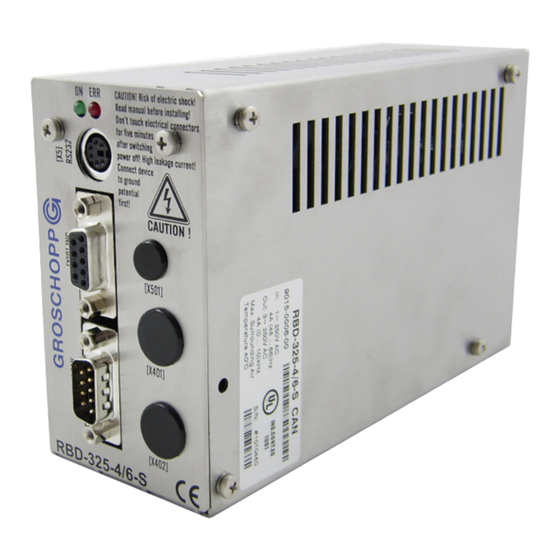
Page 170: Front Side - Dimensions - Position Connectors
Page 170 12.15.2 Front side – dimensions – position connectors ca. 27 mm ca. 35 mm ca. 62 mm Figure 34: Front side RBD 325-4/6S Manual RBD-325-4/6-S“ Version 2.0.0... -
Page 171: Back Side - Position Of The Connector
24V DC supply for Logic part [X2A] 24 V DC controlling the holding brake in motor [X2A] Connection for motor temperature sensing [X2A] Angle encoder (Resolver / Hall sensing) [X2B] Control interface with input and output (analogue / digital) Manual “RBD-325-4/6-S“ Version 2.0.0... -
Page 172: Figure 35: Back Side Rbd 325-4/6S
Page 172 Figure 35: Back side RBD 325-4/6S Manual RBD-325-4/6-S“ Version 2.0.0... -
Page 173: Side View - Dimensions - Position Of The Connectors When Using Small Mounting Plate
When mounting of the controller the minimum distances must be considered in accordance with Figure 37 to give the best cooling of the power stage of the servo position controller RBD-S. Side clearance of the device must be a minimum distance of 10 mm for good cooling. Manual “RBD-325-4/6-S“ Version 2.0.0... -
Page 174: Figure 37: Smallest Mounting Distance
Page 174 Figure 37: Minimum clearance distances of RBD-S with wall mounting Manual RBD-325-4/6-S“ Version 2.0.0... -
Page 175: 12.16 Connectors On The Rbd-S
#AIN0 -10V...10V In combination with AIN0: (DIN1) differential analogue input 0 (alternative: digital input DIN1) AIN0 -10V...10V In combination with #AIN0: (DIN0) differential analogue input 0 (alternative: digital input DIN0) Zero potential for control signals 1) Manual “RBD-325-4/6-S“ Version 2.0.0... -
Page 176: Pin Configuration: Angle Encoder And Holding Brake [X2A]
Pin configuration: Angle encoder and holding brake [X2A] The encoder interface makes it possible to connect the following encoder types and control signals: Resolver SIN-COS-Analogue signal of analogue Hall sensing (Groschopp BGK-NV motors) Holding brake in motor Temperature sensor Additionally also the 24 V logic supply connected via X2A. -
Page 177: Pin Configuration: Motor And Power Supply [X6]
320 VDC Positive potential DC-bus for brake resistor connection Power supply for the power DC-bus 230 V AC ± Power supply for the power DC-bus 230 V AC ± Connection for cable shielding from power supply Manual “RBD-325-4/6-S“ Version 2.0.0... -
Page 178: Pin Configuration: Internal Technologic Module Connection [X8]
Voltage supply technologic module max. 100 mA Data bus of DSP, address 14 All signals with Data bus of DSP, address 15 3,3 V CMOS Data bus of DSP, address 12 logic level Data bus of DSP, address 13 Manual RBD-325-4/6-S“ Version 2.0.0... - Page 179 IO- / Interrupt signal of DSP #IRQB (Sync) #IRQA IO- / Interrupt signal of DSP SPI Serial Master Output MOSI SPI Serial Clock (max. 20 MBit/s) SCLK SPI Serial Master Input MISO SPI Slave Select Reference potential Reference potential Manual “RBD-325-4/6-S“ Version 2.0.0...
-
Page 180: Pin Configuration: Can-Bus [X4]
Reference potential for the CAN-Bus, internally CAN_GND connected with GND of the 24 V logic supply CAN_HI 0 V / 5 V Signal CAN_HI in accordance with CAN-specification CAN_LO 0 V / 5 V Signal CAN_LO in accordance with CAN-specification Manual RBD-325-4/6-S“ Version 2.0.0... -
Page 181: Pin Configuration: Profibus [X401, X402]
Table 35: Pin configuration [X401, X402] Pin Nr. Designation Value Specification 0 ... 2,5 VDC Transmission Data + 0 ... 2,5 VDC Receive Data + 0 ... 2,5 VDC Transmission Data - 0 ... 2,5 VDC Receive Data - Manual “RBD-325-4/6-S“ Version 2.0.0... -
Page 182: Pin Configuration: Serial Parameterization Interface [X5]
Auxiliary supply, maximum with 50mA load +5V ± 5% 50mA n. c. 10 V / RA < Transmit wire, RS232 specification 2k Ω Figure 38: wiring communication cable RBD-S [X5] to COM port interface of the PCs Manual RBD-325-4/6-S“ Version 2.0.0... -
Page 183: Pin Configuration: Incremental Encoder In- And Output [X10]
5V / RI ≈ 120 Ω gem. RS422 Incremental encoder signal zero impulse N neg. polarity 5V / RI ≈ 120 Ω gem. RS422 Reference GND for encoder Screen for connection cable Auxiliary supply, maximum 50mA load +5V ± 5% 50mA Manual “RBD-325-4/6-S“ Version 2.0.0... -
Page 184: 12.17 Electrical Installation Of The Rbd-S
Every RBD-S should be connected to the power supply and protected by its own fuse Q1. We advise a 2 pole protection fuse (automatic). The fuses must be able to handle the peak current of the servo gear including the inrush current when switching on the power supply: Manual RBD-325-4/6-S“ Version 2.0.0... - Page 185 Also too high an auxiliary supply can disturb the devices. An excessive power voltage can exist when the zero core isn’t connected/broken in the control cabinet or externally The RBD-S controls an optional holding brake via connection [X2A], the connection of the encoders Manual “RBD-325-4/6-S“ Version 2.0.0...
- Page 186 The next notes for connecting of the motor cable and the screen apply to the motor-encoder cable of the company Groschopp. These notes are similar for the cables of other suppliers. The screen connections shown in figures 39, 40 & 42 all apply.
-
Page 187: Detail View - Connection Of Motor With Resolver [X6], [X2A]
Page 187 12.17.2 Detail view – Connection motor with resolver [X6], [X2A] Figure 40: Connection motor with resolver and holding brake Manual “RBD-325-4/6-S“ Version 2.0.0... -
Page 188: Table 38: Pin Configuration Motor Connector With Resolver
COSINUS- Level signal, differential Red/Black M_temp Motor temperature sensor PTC / KTY83 = 1 k Ω Yellow/Black Reference potential motor temperature sensor Blue/Green Reference potential for holding brake Red/Green Brake 24 V / 700 mA Control signal holding brake Manual RBD-325-4/6-S“ Version 2.0.0... -
Page 189: Detail View - Connection Of Motor With Hallsensing System [X6], [X2A]
Page 189 12.17.3 Detail view – Connection motor with Hall sensing system [X6], [X2A] Figure 42: Connection of analogue Hall sensing system and holding brake Manual “RBD-325-4/6-S“ Version 2.0.0... -
Page 190: Table 39: Pin Configuration Motor Connector With Analogue Hall Sensing System
Red/Bl M_temp Motor temperature feeler PTC / KTY83 = 1 k Ω Yellow/ Reference potential motor temperature Black sensor Blue/Gr Reference potential for holding brake Red/Gr Brake 24 V / 700 mA Control signal holding brake Manual RBD-325-4/6-S“ Version 2.0.0... -
Page 191: Connection Of Analogue And Digital In- And Output [X2B]
The connection of the supplies and motor are not shown in this picture. Refer to Figure 39 for this. Using one central star point close to the power voltage for all GND connections reduces the „ground bouncing“ effect between the controllers. Figure 44: Connection of digital and analogue I/Os Manual “RBD-325-4/6-S“ Version 2.0.0... -
Page 192: Connection: Can - Bus [X4]
On both sides of the CAN, the cable must be connected a closing resistance of 120 Ω +/- 5%. Also possible is the availability to have closing resistance in the CAN module or in the PLC. Please take note. Manual RBD-325-4/6-S“ Version 2.0.0... -
Page 193: 12.18 Notes Concerning Safe And Emc-Compliant Installation
To reduced disturbances the following points should be noted - Motor cable is not positioned parallel with the signal cables. Motor cable is in accordance with the Groschopp specification. Motor cable is screened and earthed. For more information about mounting of disturbance free CAN-Bus cables we refer to „Controller Area Network protocol specification“, Version 2.0 of Robert Bosch GmbH, 1991. -
Page 194: General Information Concerning Emc
Used two separate cables for the motor phases and angle encoder cable. Alternatively use the combination Groschopp cable for motor phases and angle encoder with spliced screen. Connect all (outside) screens with the housing of the RBD-S, and with the mounting plate, which gives a good connection to the RBD-S. - Page 195 To be sure of limited values of radiation a screened cable must be used. DANGER! All PE protected cores must on safety grounds be connected before starting the first commissioning. The rules of EN 50178 for the safety earth must certainly be considered for the installation! Manual “RBD-325-4/6-S“ Version 2.0.0...
- Page 196 Course program ..........72 Homing method ..........65 Digital inputs ............ 72 Actual position ..........69 Basic adjustments ..........60 Negative stop ........... 68 Provide program ..........74 Negative stop with zero pulse controlling ..68 Manual RBD-325-4/6-S“ Version 2.0.0...
- Page 197 Speed limitation ..........43 OK ..............118 Speed controlled operation ......49 Operation adjustment ........106 Start delay ............. 99 Optimizing Symbol list Speed controller ..........50 Offline-Online-Parameterisation ....161 Position controller ..........59 Online-Offline- Parameterisation ....161 Manual “RBD-325-4/6-S“ Version 2.0.0...
- Page 198 Quick access ........... 126 Warnings Digital output ........... 97 Target value ..........120 Remaining distance .......... 62 Temperature controlling ......... 38 Following error ..........58 Torque controlled operation......52 Torque constant ..........52 Transfer-window .......... 107 ULmarking Manual RBD-325-4/6-S“ Version 2.0.0...
Need help?
Do you have a question about the RBD-325-4/6-S and is the answer not in the manual?
Questions and answers