Sign In
Upload
Manuals
Brands
Greentrol Automation Manuals
Fan
DRI-1000-A/01B
Greentrol Automation DRI-1000-A/01B Manuals
Manuals and User Guides for Greentrol Automation DRI-1000-A/01B. We have
1
Greentrol Automation DRI-1000-A/01B manual available for free PDF download: Installation, Operation And Maintenance Manual
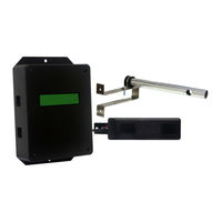
Greentrol Automation DRI-1000-A/01B Installation, Operation And Maintenance Manual (58 pages)
ENERGY RECOVERY VENTILATOR (ERV) CONTROLLER WITH COMBINATION ANALOG AND RS-485 OUTPUTS FOR DESICCANT ROTORS INTERNATIONAL – US (DRI-US)
Brand:
Greentrol Automation
| Category:
Fan
| Size: 2 MB
Table of Contents
Table of Contents
3
Scope
6
Overview
6
Figure 1. DRI-1000-A ERV Controller System Components
6
Table 1. DRI-1000-A Models and Sensor Configuration Matrix
7
Dri-1000-A Specifications
8
Model DRI-1000-A Controller Mechanical Details
10
Figure 2. DRI-1000-A Controller/Display Unit Mechanical Detail
10
Rh/Temperature Sensor Model GS-2Xx-P/RH/T
11
Figure 3. Rh/Temperature Sensor Mechanical Detail
11
Air Flow Probe Model S-110/01/10
12
Figure 4. S-110 Airflow Probe and Universal Bracket Detail Views
12
Dri-1000-A Features
13
DRI-1000-A Controller/Display Unit
13
RH/T Sensor Assemblies
14
Airflow Probes
14
Figure 5. DRI-1000-A Controller/Display Unit Detail View
14
Installation
15
Pre-Installation Site Survey and Planning
15
RH/T Sensor Installation
15
Figure 6. RH/T Sensor Detail View
15
Figure 7. Airflow Probe and Universal Bracket Detail View
15
Optional Air Flow Probe Installation
17
ERV Wheel Speed Sensor Installation
19
Setting the SENSOR TYPE Jumper
19
Figure 8. Typical S-110 Airflow Probe Placement Detail
19
Controller/Display Unit Installation
20
System Wiring and Interconnections
21
Power Transformer Selection Considerations
21
DRI-1000-A Wiring Precautions
21
24VAC Power Connections
23
AOUT1, AOUT2 - Analog Output Connections
23
Figure 9. DRI-1000-A ERV System Controller Typical Wiring Diagram
23
RS-485 Network Connections
24
Setting DRI-1000-A Network Termination
24
Setting Transmitter Address
24
Setting MS/TP Baud Rate
24
Setting Device Instance Number
24
Resetting Communications Options to Default
24
RS-485 Network Connections and Device Settings
25
Bacnet Objects List and Properties
26
Table 2. RS-485 Bacnet Object Properties
27
ALARM Output Connections
28
Setting the Alarm LED PWR Jumper
28
Connecting Sensors to the DRI-1000-A Controller/Display Unit
28
RH/T Sensor Connections
28
Wheel Speed Sensor Connections
29
Air Flow Probe Connections
29
Final Inspection/Cable Routing and Management
29
Initial Start-Up
30
Dri-1000-A Set up and Device Configuration
31
DRI-1000-A SETUP Menu Options and Navigation
31
Table 3. DRI-1000-A Major Menus
31
SYSTEM INIT Menu - System Initialization Menu (Restore Factory Default Settings)
32
SYSTEM INIT Menu - Factory Default Values
32
IP/SI UNITS Menu - System Units of Measurement Menu for IP SYS and si SYS
33
Figure 10. SYSTEM INIT - Initialization Menu Detail
33
Figure 11. SYSTEM INIT Menu - Factory Default Values
33
Table 4. IP/SI Units of Measurement
33
SETUP Menu - System Setup Menu
34
Figure 12. IP/SI UNITS - Units of Measurement Menu Detail
34
Figure 13. SETUP - System Setup Menu Detail
35
SETUP Menu - Factory Default Values
37
COMM SETUP Menu - RS-485 Communications Setup Menu
38
Figure 14. SETUP Menu - Factory Default Values
38
Figure 15. COMM SETUP - RS-485 Communications Setup Menu Detail
39
DIAGNOSTICS Menu
40
Figure 16. DIAGNOSTICS Menu - Sensor and System Status Menu Detail
40
Figure 17. DIAGNOSTICS Menu - Menu Item Detail
41
LOCK Menu
42
Figure 18. LOCK - Menu Detail
42
DRI-1000-A Alarm Set up
43
Programmable Alarm Indications
43
Table 5. Alarm Types and Descriptions
43
Deadband Alarm - "ALR TYP = DEADB
44
Figure 19. Deadband Alarm Example
44
High Limit Alarm - "ALR TYP = HI
45
Figure 20. High Limit Alarm Example
45
Lo Limit Alarm - "ALR TYP = lo
46
Figure 21. Low Limit Alarm Example
46
Alarm Hysteresis - "HYS
47
Alarm Polarity - "ALRM POL=NO
47
Trouble Alarm - ALRM TYP=TRBL
47
ERV Wheel Speed Rotation Alarm - "ALR TYP=SPEED
47
Normal Operating Instructions
47
DRI-1000-A LCD Display Features
47
Display Hold/Resume Feature
47
Field Adjustments
48
Manual Adjustment of Factory OFFSET/GAIN Calibration
48
Procedure for 1 Point Field Adjustment
48
Procedure for 2 Point Field Adjustment
49
FLOWFIL - Engaging and Adjusting the Digital Airflow Output Filter
50
FLOW BUF - Flow Buffer
50
INT TIM - Integration Time
50
INT NUM - Integration Number
50
ECO MODE - Setting the Economizer Mode
50
ECO1 - Economizer 1 Mode
50
ECO2 - Economizer 2 Mode
50
LL2 - Adjusting the Low Limit Cutoff
50
Adjusting the PID Loop Values
51
Output Scaling
51
Principles of Operation
52
System Overview
52
Figure 22. Block Diagram of Typical DRI-1000-A ERV Controller System and DRI ERV System
53
System Firmware Overview
54
Figure 23. Functional Block Diagram of DRI-1000-A ERV Controller System Operation
54
System Modes of Operation
55
Summer Mode (OA Temperature > 32 F)
55
Winter (Frost) Mode
55
Failure Modes
55
LCD Display Indications
56
Maintenance
57
Table 6. DRI-1000-A Troubleshooting Guide
57
Oem Standard Limited Parts Warranty
58
Advertisement
Advertisement
Related Products
Greentrol Automation DRI-1000-A
Greentrol Automation DRI-1000-A/01A
Greentrol Automation DRI-1000-A/01A/A
Greentrol Automation DRI-1000-A/01B/A
Greentrol Automation DRI-1000-A/02
Greentrol Automation DRI-1000-A/02A
Greentrol Automation Categories
Measuring Instruments
Fan
Cash Counter
More Greentrol Automation Manuals
Login
Sign In
OR
Sign in with Facebook
Sign in with Google
Upload manual
Upload from disk
Upload from URL