Table of Contents
Advertisement
Quick Links
Installation, Operation and
Maintenance Technical Manual
MODEL DRI-1000-A
ENERGY RECOVERY VENTILATOR (ERV) CONTROLLER
WITH COMBINATION ANALOG AND RS-485 OUTPUTS FOR
DESICCANT ROTORS INTERNATIONAL – US (DRI-US)
Document TM_DRI-1000-A-OEM
Revision R2A
©
GreenTrol Automation, Inc. · 156 Holly View Lane Loris, SC 29569 · Toll Free: 877-4GN-TROL (877.446.8765) · Internet: GreenTrol.com
Advertisement
Table of Contents

Summary of Contents for Greentrol Automation DRI-1000-A
- Page 1 ENERGY RECOVERY VENTILATOR (ERV) CONTROLLER WITH COMBINATION ANALOG AND RS-485 OUTPUTS FOR DESICCANT ROTORS INTERNATIONAL – US (DRI-US) Document TM_DRI-1000-A-OEM Revision R2A © GreenTrol Automation, Inc. · 156 Holly View Lane Loris, SC 29569 · Toll Free: 877-4GN-TROL (877.446.8765) · Internet: GreenTrol.com...
- Page 2 RS-485 changes..........07/01/2011 Figure 2 replaced with correct mechanical detail....05/19/2011 1 through 50 Initial document release............08/25/2010 2 of © GreenTrol Automation, Inc. · 156 Holly View Lane Loris, SC 29569 · Toll Free: 877-4GN-TROL (877.446.8765) · Internet: GreenTrol.com...
-
Page 3: Table Of Contents
ERV Wheel Speed Rotation Alarm – “ALR TYP=SPEED.................45 NORMAL OPERATING INSTRUCTIONS......................45 8.1. DRI-1000-A LCD Display Features........................45 8.1.1. Display Hold/Resume Feature.......................... 45 3 of © GreenTrol Automation, Inc. · 156 Holly View Lane Loris, SC 29569 · Toll Free: 877-4GN-TROL (877.446.8765) · Internet: GreenTrol.com... - Page 4 Table 4. IP/SI Units of Measurement..........................32 Table 5. Alarm Types and Descriptions......................... 41 Table 6. DRI-1000-A Troubleshooting Guide......................... 55 4 of © GreenTrol Automation, Inc. · 156 Holly View Lane Loris, SC 29569 · Toll Free: 877-4GN-TROL (877.446.8765) · Internet: GreenTrol.com...
- Page 5 5 of © GreenTrol Automation, Inc. · 156 Holly View Lane Loris, SC 29569 · Toll Free: 877-4GN-TROL (877.446.8765) · Internet: GreenTrol.com...
-
Page 6: Scope
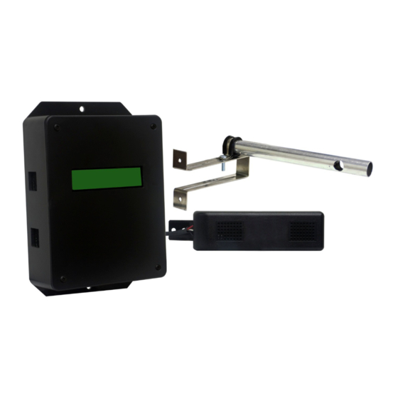
N.C.) or direct LED drive current (15 mA typical) for a wide range of alarm interfaces. The DRI-1000-A is available with optional air flow probes and RH/T sensors as shown in Figure 1. Table 1 lists the system model codes and the sensors/probe complement provided with each model. -
Page 7: Table 1. Dri-1000-A Models And Sensor Configuration Matrix
(1) GS-212-P/RH/T (EX) (1) GS-213-P/RH/T (SA) DRI-1000-A/02A (1) GS-210-P/RH/T (OA) (1) GS-211-P/RH/T (RA) (1) GS-212-P/RH/T (EX) (No SA RH/T Sensor) 7 of © GreenTrol Automation, Inc. · 156 Holly View Lane Loris, SC 29569 · Toll Free: 877-4GN-TROL (877.446.8765) · Internet: GreenTrol.com... -
Page 8: Dri-1000-A Specifications
Overall depth with integral mounting flanges is 4.57 in [116.08 mm] Air Flow Sensor Probe (optional for OA and EX air flows): 8 of © GreenTrol Automation, Inc. · 156 Holly View Lane Loris, SC 29569 · Toll Free: 877-4GN-TROL (877.446.8765) · Internet: GreenTrol.com... - Page 9 1. Dry relay contacts; 30VDC/24VAC, 3A max; or as direct LED drive (15 mA typ) 2. Local flashing LCD display indicating alarm condition 9 of © GreenTrol Automation, Inc. · 156 Holly View Lane Loris, SC 29569 · Toll Free: 877-4GN-TROL (877.446.8765) · Internet: GreenTrol.com...
-
Page 10: Model Dri-1000-A Controller Mechanical Details
0.785 (19.94) BOTTOM END ONLY 2X 0.625 (15.88) DIA 4.338 (110.19) Figure 2. DRI-1000-A Controller/Display Unit Mechanical Detail 10 of © GreenTrol Automation, Inc. · 156 Holly View Lane Loris, SC 29569 · Toll Free: 877-4GN-TROL (877.446.8765) · Internet: GreenTrol.com... -
Page 11: Rh/Temperature Sensor Model Gs-2Xx-P/Rh/T
DRI-1000-A CONTROLLER 0.32 (8.13) 0.58 (14.73) 0.38 (9.65) 1.1794 3.83 (97.28) (29.72) Figure 3. RH/Temperature Sensor Mechanical Detail 11 of © GreenTrol Automation, Inc. · 156 Holly View Lane Loris, SC 29569 · Toll Free: 877-4GN-TROL (877.446.8765) · Internet: GreenTrol.com... -
Page 12: Air Flow Probe Model S-110/01/10
FRONT SIDE HARDWARE VIEW VIEW (27.9) 3.00 (76.2) Figure 4. S-110 Airflow Probe and Universal Bracket Detail Views 12 of © GreenTrol Automation, Inc. · 156 Holly View Lane Loris, SC 29569 · Toll Free: 877-4GN-TROL (877.446.8765) · Internet: GreenTrol.com... -
Page 13: Dri-1000-A Features
TERMINATION SELECT PROBE PROBE MENU/SETUP CONFIGURATION PUSH BUTTONS AIRFLOW PROBE CONNECTORS Figure 3. DRI-1000-A Controller/Display Unit Detail View 13 of © GreenTrol Automation, Inc. · 156 Holly View Lane Loris, SC 29569 · Toll Free: 877-4GN-TROL (877.446.8765) · Internet: GreenTrol.com... -
Page 14: Rh/T Sensor Assemblies
SENSOR CABLE BEAD IN GLASS AND PRECISION SENSOR ELEMENTS Figure 5. Airflow Probe and Universal Bracket Detail View 14 of © GreenTrol Automation, Inc. · 156 Holly View Lane Loris, SC 29569 · Toll Free: 877-4GN-TROL (877.446.8765) · Internet: GreenTrol.com... -
Page 15: Installation
DRI-1000-A Controller/Display unit will allow visibility of the LCD display and access to the internal DRI-1000-A for wiring and set up via the four board-mounted push button switches. 15 of © GreenTrol Automation, Inc. · 156 Holly View Lane Loris, SC 29569 · Toll Free: 877-4GN-TROL (877.446.8765) · Internet: GreenTrol.com... - Page 16 5.2. RH/T Sensor Installation The DRI-1000-A is supplied with 3 or 4 RH/T sensors (Figure 3) depending on the model selected as shown in Table 1. The location of the individual RH/T sensors is critical for proper operation of the system.
-
Page 17: Optional Air Flow Probe Installation
Optional model S-110 airflow probes may be included for EX and/or OA airflow measurement depending upon which DRI-1000-A model is provided (see Table 1). If airflow probes are not included in the model provided, skip this procedure and proceed directly to ERV Wheel Sensor Installation. - Page 18 ERV cabinet covers, mechanical slides, etc. 7. Mark the connector end of the OA probe cable “OA” with a suitable permanent marker. 18 of © GreenTrol Automation, Inc. · 156 Holly View Lane Loris, SC 29569 · Toll Free: 877-4GN-TROL (877.446.8765) · Internet: GreenTrol.com...
-
Page 19: Erv Wheel Speed Sensor Installation
This completes installation of the customer provided wheel speed sensor. Proceed to install the DRI-1000-A Controller/Display unit as outlined in the following paragraph. 19 of © GreenTrol Automation, Inc. · 156 Holly View Lane Loris, SC 29569 · Toll Free: 877-4GN-TROL (877.446.8765) · Internet: GreenTrol.com... -
Page 20: Controller/Display Unit Installation
The DRI-1000-A is designed for use in an environment between -20 and 120°F (-28.8 and 48.8°C) where it will not be exposed to precipitation. A NEMA-4 enclosure must be provided to protect the DRI-1000-A in locations where precipitation may be encountered. -
Page 21: System Wiring And Interconnections
To prevent any potential water runoff into the DRI-1000, form “drip loops” with interconnecting cables below the connections to the DRI-1000-A. 21 of © GreenTrol Automation, Inc. · 156 Holly View Lane Loris, SC 29569 · Toll Free: 877-4GN-TROL (877.446.8765) · Internet: GreenTrol.com... - Page 22 1: CONNECT ANALOG AND RS-485 CABLE DRAINS TO EARTH GROUND AT ONE END OF CABLE ONLY. 2. DRI-1000-A IS NON-ISOLATED USING A HALF-WAVE RECTIFIER ON 24VAC POWER INPUT. IF MULTIPLE DEVICES ARE POWERED BY COMMON TRANSFORMER, ALL GND CONNECTIONS MUST BE COMMON, OR AN ISOLATION TRANSFORMER MUST BE USED TO PREVENT EQUIPMENT DAMAGE.
-
Page 23: 24Vac Power Connections
) at the AOUT2 terminal, and the corresponding AOUT2 signal return at the GND (AOUT COM) terminal as shown in Figure 5, observing the previous precautions. 23 of © GreenTrol Automation, Inc. · 156 Holly View Lane Loris, SC 29569 · Toll Free: 877-4GN-TROL (877.446.8765) · Internet: GreenTrol.com... -
Page 24: Rs-485 Network Connections
COMM setup menu (Figure 15). 6.5.3. Setting MS/TP Baud Rate The DRI-1000-A is set at the factory for MS/TP with a baud rate of 76,800 that can be changed if required using the Communications menu (Figure 15). 6.5.4. Setting Device Instance Number The DRI-1000-A is factory set with a Device Instance Number of 2. -
Page 25: Rs-485 Network Connections And Device Settings
NO TERMINATION. If the DRI-1000-A is the first or last device, ensure that TERMINATION jumper is installed for END OF LINE termination as previously described. 25 of © GreenTrol Automation, Inc. · 156 Holly View Lane Loris, SC 29569 · Toll Free: 877-4GN-TROL (877.446.8765) · Internet: GreenTrol.com... -
Page 26: Bacnet Objects List And Properties
- Alarm Status Modes: None RH/T Sensor Speed Sensor Probe Trouble OA Flow LO OA Flow HI 26 of © GreenTrol Automation, Inc. · 156 Holly View Lane Loris, SC 29569 · Toll Free: 877-4GN-TROL (877.446.8765) · Internet: GreenTrol.com... -
Page 27: Table 2. Rs-485 Bacnet Object Properties
State Text Multi-state Value 2 – Description None Reliability Alarm Status State Text 27 of © GreenTrol Automation, Inc. · 156 Holly View Lane Loris, SC 29569 · Toll Free: 877-4GN-TROL (877.446.8765) · Internet: GreenTrol.com... -
Page 28: Alarm Output Connections
ALARM Output Connections The DRI-1000-A alarm output can be configured as relay dry contacts, or as direct drive (15 mA typical) for an external LED indicator. The alarm output type is set using the LED PWR jumper on the DRI-1000- A main circuit board as shown in Figure 5. -
Page 29: Wheel Speed Sensor Connections
ERV enthalpy wheel rotation. The SPEED SELECTOR TYPE SENSOR jumper (NPN/PNP) on the DRI-1000-A must also be set to match the output polarity of the E2F sensor model selected. Connect the sensor at the SPEED SENSOR CONNECTIONS terminal block shown in Figure 5 as follows: 1. -
Page 30: Initial Start-Up
If the prior steps have been successfully accomplished, proceed to DRI-1000-A SET UP AND DEVICE CONFIGURATION as outlined in the following paragraphs. 30 of © GreenTrol Automation, Inc. · 156 Holly View Lane Loris, SC 29569 · Toll Free: 877-4GN-TROL (877.446.8765) · Internet: GreenTrol.com... -
Page 31: Dri-1000-A Set Up And Device Configuration
DRI-1000-A settings. The following paragraphs detail each of the major menus and the options available for each menu item. 31 of © GreenTrol Automation, Inc. · 156 Holly View Lane Loris, SC 29569 · Toll Free: 877-4GN-TROL (877.446.8765) · Internet: GreenTrol.com... -
Page 32: System Init Menu - System Initialization Menu (Restore Factory Default Settings)
Figure 9. SYSTEM INIT Menu – Factory Default Values 32 of © GreenTrol Automation, Inc. · 156 Holly View Lane Loris, SC 29569 · Toll Free: 877-4GN-TROL (877.446.8765) · Internet: GreenTrol.com... -
Page 33: Ip/Si Units Menu - System Units Of Measurement Menu For Ip Sys And Si Sys
IP/SI UNITS Menu - System Units of Measurement Menu for IP SYS and SI SYS The DRI-1000-A is shipped with the IP/SI system of units set to IP (US inch-pound) units, and will display units of measurement as shown in the “IP” System of Units column of Table 4. -
Page 34: Setup Menu - System Setup Menu
Figure 13 shows the SETUP menu (with IP SYS units of measure). Figure 11. SETUP – System Setup Menu Detail 34 of © GreenTrol Automation, Inc. · 156 Holly View Lane Loris, SC 29569 · Toll Free: 877-4GN-TROL (877.446.8765) · Internet: GreenTrol.com... -
Page 35: Figure 13. Setup - System Setup Menu Detail
Figure 13. SETUP (continued) – System Setup Menu Detail (2 of 3) 35 of © GreenTrol Automation, Inc. · 156 Holly View Lane Loris, SC 29569 · Toll Free: 877-4GN-TROL (877.446.8765) · Internet: GreenTrol.com... - Page 36 Figure 13. SETUP (continued) – System Setup Menu Detail (3 of 3) 36 of © GreenTrol Automation, Inc. · 156 Holly View Lane Loris, SC 29569 · Toll Free: 877-4GN-TROL (877.446.8765) · Internet: GreenTrol.com...
-
Page 37: Setup Menu - Factory Default Values
If Td of -5 degrees is used, Analog OUT2 value = (-5/FS2 range)+(1/2 x OUT2 voltage range) or (- 5/40)+(1/2 x 10V) = -0.125 + 5= 4.875. Figure 12. SETUP Menu – Factory Default Values 37 of © GreenTrol Automation, Inc. · 156 Holly View Lane Loris, SC 29569 · Toll Free: 877-4GN-TROL (877.446.8765) · Internet: GreenTrol.com... -
Page 38: Comm Setup Menu - Rs-485 Communications Setup Menu
Figure 15 shows the DRI-1000-A COMM SETUP menu and available options. 38 of © GreenTrol Automation, Inc. · 156 Holly View Lane Loris, SC 29569 · Toll Free: 877-4GN-TROL (877.446.8765) · Internet: GreenTrol.com Figure 13. COMM SETUP – RS-485 Communications Setup Menu Detail... -
Page 39: Figure 15. Comm Setup - Rs-485 Communications Setup Menu Detail
YES Re-sets co mmunicatio n values to initial facto ry default settings. NO DIAGNOSTICS DIAGNOSTIC MENU 39 of © GreenTrol Automation, Inc. · 156 Holly View Lane Loris, SC 29569 · Toll Free: 877-4GN-TROL (877.446.8765) · Internet: GreenTrol.com... -
Page 40: Diagnostics Menu
DIAGNOSTICS menu. Figure 17 details each of the Diagnostics menu items. Figure 14. DIAGNOSTICS Menu – Sensor and System Status Menu Detail 40 of © GreenTrol Automation, Inc. · 156 Holly View Lane Loris, SC 29569 · Toll Free: 877-4GN-TROL (877.446.8765) · Internet: GreenTrol.com... -
Page 41: Figure 17. Diagnostics Menu - Menu Item Detail
Figure 15. DIAGNOSTICS Menu – Menu Item Detail 41 of © GreenTrol Automation, Inc. · 156 Holly View Lane Loris, SC 29569 · Toll Free: 877-4GN-TROL (877.446.8765) · Internet: GreenTrol.com... -
Page 42: Lock Menu
The LOCK menu allows the current configuration settings to be locked to prevent unauthorized changes to DRI-1000-A settings. Once the user defined lock code from 1 to 9999 is established, all user defined DRI-1000-A settings can only be altered after the lock code is entered. Figure 18 shows the LOCK menu detail. -
Page 43: Dri-1000-A Alarm Set Up
“TROUBLE” during the Alarm sensors or probes. Status display cycle. Use DIAGNOSTICS menu to determine fault. 43 of © GreenTrol Automation, Inc. · 156 Holly View Lane Loris, SC 29569 · Toll Free: 877-4GN-TROL (877.446.8765) · Internet: GreenTrol.com... -
Page 44: Deadband Alarm - "Alr Typ = Deadb
ALARM HYSTERESIS VALUE 1,000 “ALRM HYS=20%” ALARM ACTIVE ALARM RESET (ON) (OFF) Figure 17. Deadband Alarm Example TIME 44 of © GreenTrol Automation, Inc. · 156 Holly View Lane Loris, SC 29569 · Toll Free: 877-4GN-TROL (877.446.8765) · Internet: GreenTrol.com... -
Page 45: High Limit Alarm - "Alr Typ = Hi
“ASP=1000 ” “ALRM HYS=20%” 1,000 ALARM RESET ALARM ACTIVE (OFF) (ON) Figure 18. High Limit Alarm Example TIME 45 of © GreenTrol Automation, Inc. · 156 Holly View Lane Loris, SC 29569 · Toll Free: 877-4GN-TROL (877.446.8765) · Internet: GreenTrol.com... -
Page 46: Lo Limit Alarm - "Alr Typ = Lo
ALARM HYSTERESIS VALUE “ALRM HYS=20%” ALARM SET POINT VALUE “ASP=1000 ” TIME Figure 19. Low Limit Alarm Example 46 of © GreenTrol Automation, Inc. · 156 Holly View Lane Loris, SC 29569 · Toll Free: 877-4GN-TROL (877.446.8765) · Internet: GreenTrol.com... -
Page 47: Alarm Hysteresis - "Hys
(DRI based calculation when equipped with optional SA RH/T sensor), the alarm status and the operating mode of the DRI-1000-A system. The LCD will display each of the items for 3 seconds, and then step to the next item and repeat this cycle: Outside Airflow Rate (if OA airflow probe is connected and enabled in the setup menu). -
Page 48: Field Adjustments
GAIN/OFFSET is required, perform manual adjustment of the factory calibration at one or two points. The DRI-1000-A firmware can only be adjusted for analog OUT2 (OA airflow) signal “gain” and “offset”. To adjust the output signal “gain”, the “OFF-GAIN2” menu item must be set to “*OFF- GAIN2=ON”... -
Page 49: Procedure For 2 Point Field Adjustment
15. Press the “ESC” button until the normal operating mode and display are restored. 2-Point Field Adjustment is complete. 49 of © GreenTrol Automation, Inc. · 156 Holly View Lane Loris, SC 29569 · Toll Free: 877-4GN-TROL (877.446.8765) · Internet: GreenTrol.com... -
Page 50: Flowfil - Engaging And Adjusting The Digital Airflow Output Filter
To set the low limit cutoff, enter the Setup menu and set “*LL1={desired value in FPM (MPS in SI units)}” as shown in Figure 13. 50 of © GreenTrol Automation, Inc. · 156 Holly View Lane Loris, SC 29569 · Toll Free: 877-4GN-TROL (877.446.8765) · Internet: GreenTrol.com... -
Page 51: Adjusting The Pid Loop Values
Factory default output scaling can be changed by entering the setup menu shown in Figure 13. 51 of © GreenTrol Automation, Inc. · 156 Holly View Lane Loris, SC 29569 · Toll Free: 877-4GN-TROL (877.446.8765) · Internet: GreenTrol.com... -
Page 52: Principles Of Operation
LCD display is also used in conjunction with convenient board-mounted tactile push button switches for simple field configuration and set up of the DRI-1000-A. An RS-485 port is provided for BACnet operation. 52 of © GreenTrol Automation, Inc. · 156 Holly View Lane Loris, SC 29569 · Toll Free: 877-4GN-TROL (877.446.8765) · Internet: GreenTrol.com... -
Page 53: Figure 22. Block Diagram Of Typical Dri-1000-A Erv Controller System And Dri Erv System
RS-485 OUT OUTPUT DRI-1000-A CONTROLLER Figure 20. Block Diagram of Typical DRI-1000-A ERV Controller System and DRI ERV System 53 of © GreenTrol Automation, Inc. · 156 Holly View Lane Loris, SC 29569 · Toll Free: 877-4GN-TROL (877.446.8765) · Internet: GreenTrol.com... -
Page 54: System Firmware Overview
(SEE ABOVE) (SEE ABOVE) RETURN TO START Figure 21. Functional Block Diagram of DRI-1000-A ERV Controller System Operation 54 of © GreenTrol Automation, Inc. · 156 Holly View Lane Loris, SC 29569 · Toll Free: 877-4GN-TROL (877.446.8765) · Internet: GreenTrol.com... -
Page 55: System Modes Of Operation
If summer mode operation can be confirmed via the OA sensor temperature (OA sensor is working), then the DRI-1000-A will run the wheel at full speed. If winter mode can be confirmed via the OA sensor, then the DRI-1000-A will run the wheel at minimum speed. -
Page 56: Lcd Display Indications
Alarm Status (NONE, RH/T SENSOR, OA LOW, OA HIGH, PRB TRBL, or SPEED); Operational Mode (ECO1, ECO2, NORMAL, FROST, or FAILURE); 56 of © GreenTrol Automation, Inc. · 156 Holly View Lane Loris, SC 29569 · Toll Free: 877-4GN-TROL (877.446.8765) · Internet: GreenTrol.com... -
Page 57: Maintenance
2-second intervals. system has detected a connections contact malfunction. customer service further assistance. (continued) 57 of © GreenTrol Automation, Inc. · 156 Holly View Lane Loris, SC 29569 · Toll Free: 877-4GN-TROL (877.446.8765) · Internet: GreenTrol.com... -
Page 58: Oem Standard Limited Parts Warranty
The DRI-1000-A is warranted for 12 months from shipment to the original equipment manufacturer only. Product will be repaired/replaced free of charge as described in the Terms and Conditions of Sale. 58 of © GreenTrol Automation, Inc. · 156 Holly View Lane Loris, SC 29569 · Toll Free: 877-4GN-TROL (877.446.8765) · Internet: GreenTrol.com...
Need help?
Do you have a question about the DRI-1000-A and is the answer not in the manual?
Questions and answers