Gree GC201306-I Air Conditioner Manuals
Manuals and User Guides for Gree GC201306-I Air Conditioner. We have 3 Gree GC201306-I Air Conditioner manuals available for free PDF download: Service Manual
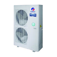
Gree GC201306-I Service Manual (217 pages)
SUPER FREE MATCH SERIES T1/R410A/50Hz
Brand: Gree
|
Category: Air Conditioner
|
Size: 9 MB
Table of Contents
Advertisement
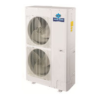
Gree GC201306-I Service Manual (183 pages)
CENTRAL AIR CONDITIONERS R410A T1/R410A/60Hz
Brand: Gree
|
Category: Air Conditioner
|
Size: 35 MB
Table of Contents
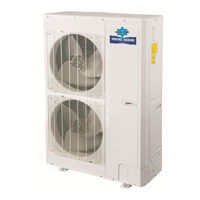
Gree GC201306-I Service Manual (183 pages)
Central Air Conditioners R410A T1/R410A/60Hz
Brand: Gree
|
Category: Air Conditioner
|
Size: 20 MB
Table of Contents
Advertisement
Advertisement