Sign In
Upload
Manuals
Brands
GOWIN Manuals
Motherboard
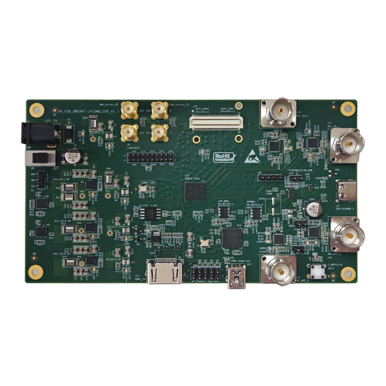
DK USB GW5ART-LV15MG132P V1.1
GOWIN DK USB GW5ART-LV15MG132P V1.1 Manuals
Manuals and User Guides for GOWIN DK USB GW5ART-LV15MG132P V1.1. We have
1
GOWIN DK USB GW5ART-LV15MG132P V1.1 manual available for free PDF download: User Manual
GOWIN DK USB GW5ART-LV15MG132P V1.1 User Manual (30 pages)
Brand:
GOWIN
| Category:
Motherboard
| Size: 1 MB
Table of Contents
Table of Contents
4
List of Figures
6
About this Guide
8
Purpose
8
Related Documents
8
Terminology and Abbreviations
9
Support and Feedback
9
Table 1-1 Terminology and Abbreviations
9
Development Board Introduction
10
Overview
10
Figure 2-1 DK_USB_GW5ART-LV15MG132P_V1.1 Development Board
10
A Development Board Kit
11
Figure 2-2 a Development Board Kit
11
PCB Components
12
System Block Diagram
12
Figure 2-3 PCB Components
12
Figure 2-4 System Block Diagram
12
Features
13
Development Board Circuit
15
Fpga
15
Overview
15
I/O BANK Introduction
15
Power Supply
15
Introduction
15
Power Distribution
16
Figure 3-1 Power Distribution Diagram
16
Download Module
17
Introduction
17
Pin Distribution
17
Clock
17
Figure 3-2 Connection Diagram of Download
17
Figure 3-3 Clock Connection Diagram
17
Table 3-1 JTAG Pin Distribution
17
Pin Distribution
18
I2C Interface
18
Introduction
18
Figure 3-4 Connection Diagram of I2C Interface
18
Table 3-2 Clock Pin Distribution
18
Pin Distribution
19
MIPI Interface
19
Introduction
19
Figure 3-5 Connection Diagram of MIPI CPHY & DPHY Hard Core Interfaces
19
Figure 3-6 Connection Diagram of MIPI DPHY Soft Core/Lvds Interface
19
Table 3-3 Pin Distribution of I2C Interface
19
Pin Distribution
20
Table 3-4 Pin Distribution of MIPI CPHY & DPHY Hard Core Interface
20
Table 3-5 Pin Distribution of MIPI DPHY Soft Core/Lvds Interface
23
HDMI Interface
24
Introduction
24
Pin Distribution
24
Figure 3-7 Connection Diagram of HDMI-RX Interface
24
Table 3-6 Pin Distribution of HDMI-RX
24
SPI Interface
25
Introduction
25
Pin Distribution
25
Type-C Interface
25
Figure 3-8 Connection Diagram of SPI Interface
25
Table 3-7 Pin Distribution of SPI Interface
25
Pin Distribution
26
SDI Interface
26
Introduction
26
Figure 3-9 Connection Diagram of Type-C Interface
26
Table 3-8 Pin Distribution of Type-C Interface
26
Pin Distribution
27
Figure 3-10 Connection Diagram of SDI Interface
27
Table 3-9 Pin Distribution of SDI Interface
27
Key
28
Introduction
28
Pin Distribution
28
Figure 3-11 Connection Diagram of Key
28
Table 3-10 Pin Distribution of Key
28
SMA Interface
29
Introduction
29
Pin Distribution
29
Figure 3-12 Connection Diagram of SMA Interface
29
Table 3-11 Pin Distribution of SMA Interface
29
Advertisement
Advertisement
Related Products
GOWIN DK START GW5ASTLV138FPG676A V1.0
GOWIN DK VIDEO GW5AT-LV60UG225 V1.0
GOWIN GW1NS-4C
GOWIN GW1N-LV9LQ144C6I5 V1.1
GOWIN DK START GW1NZ-LV1FN32C6I5
GOWIN GW1NSER-4C QN48P
GOWIN DK START GW1N LV4LQ144C6I5 V1.1
GOWIN DK START GW2AR18 V1.1
GOWIN DK START GW1NS-LV4CQN48C7I6 V1.1
GOWIN GW1NSER-4C
GOWIN Categories
Motherboard
Semiconductors
Computer Hardware
Microcontrollers
Recording Equipment
More GOWIN Manuals
Login
Sign In
OR
Sign in with Facebook
Sign in with Google
Upload manual
Upload from disk
Upload from URL