Sign In
Upload
Manuals
Brands
GORBEL Manuals
Lifting Systems
G-Force iQ2 Series
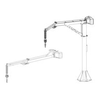
GORBEL G-Force iQ2 Series Lifting Device Manuals
Manuals and User Guides for GORBEL G-Force iQ2 Series Lifting Device. We have
3
GORBEL G-Force iQ2 Series Lifting Device manuals available for free PDF download: Service Manual, Installation, Operation & Maintenance Manual
GORBEL G-Force iQ2 Series Service Manual (138 pages)
Brand:
GORBEL
| Category:
Industrial Equipment
| Size: 5 MB
Table of Contents
Table of Contents
3
Chapter 1 - Safe Hoist Operating Guidelines
5
Chapter 2 - Technical Specifications
6
Chapter 3 - Removal Procedure
8
Chapter 4 - Control and Programming
9
Chapter 5 - Software Field Upgrade
15
Chapter 6 - Troubleshooting
20
Troubleshooting Procedure
20
Troubleshooting Section I: Functional Failure Table
22
Troubleshooting Section II: System Fault Diagnostics Chart
26
Q2-Iq2 Fault/Error/Warning Code Corrective Actions
28
Chapter 7 - Electrical Schematics
40
Chapter 8 - Adjustments
49
Limit Switch Adjustment
49
Wire Rope Replacement Adjustment
50
Linear Transducer Adjustment
51
Slack Spring Adjustment
52
Chapter 9 - Parts and Assembly
55
Actuator
55
Sliding Handle
84
Pendant Handle
93
Force Sensing Handle
106
Coil Cords
114
Easy Arm Components
124
Advertisement
GORBEL G-Force iQ2 Series Installation, Operation & Maintenance Manual (92 pages)
Brand:
GORBEL
| Category:
Controller
| Size: 7 MB
Table of Contents
Table of Contents
2
Safe Hoist Operating Guidelines
3
Warnings & Introduction
5
Correct G-Force® Installation Orientation
7
G-Force® Main Assembly Component Description
8
Installation
9
Step 1 - Unpacking the G-Force
9
Step 2 - Pre-Assembly / Tools Required
9
Step 3 - Actuator Assembly Installation
9
Step 4 - Coil Cord Installation
10
Step 5A - In-Line Slide & Force Sensing Slide Handle Installation
11
Step 5B - Remote Mounted Slide Handle Installation
11
Step 5C - Suspended Pendant Handle Installation
13
Step 5D - Remote Mounted Pendant Handle Installation
14
Step 5E - 1320 Lb. In-Line Slide or Remote Mounted Handle Installation
15
Step 5F - 1320 Lb. Suspended Pendant Handle Installation
16
Step 5G - 1320 Lb. Air Hose Installation (Option)
17
Step 5H - Remote Mount Force Sensing Slide Handle Installation
18
Step 5I - Remote Mount Force Sensing Hub Handle Installation
19
Step 6 - Electrical Power Connection
20
Step 7 - Initial Power-Up
20
Step
21
Step 9 - Expansion I/O Block Mounting Instructions (Option)
23
Lift Functionality
24
Controls Interface Features
27
Program Mode
28
Overview & Basic Features
28
Menu and Sub-Menu Selections
30
Program Mode Menus and Explanations
30
Troubleshooting
47
Basic Troubleshooting
47
LED Status Chart
49
Technical Specifications
50
Wire Rope Inspection, Maintenance, & Replacement
51
Slack Spring Adjustment
58
Recommended Spare Parts Kits
59
Dual Handle Setup Instructions
60
G-Force® HMI Visualization
62
Appendix A: AP Field Customization Instructions
81
Appendix B: AP VNC Viewer Install Instructions
84
Appendix C: AP Connection Quickstart Guide
86
Appendix F: PC IP Address Set up for Wired Connections
88
Limited Warranty
90
CE Declaration of Conformity
91
Inspection and Maintenance Schedule
92
GORBEL G-Force iQ2 Series Installation, Operation & Maintenance Manual (90 pages)
Brand:
GORBEL
| Category:
Lifting Systems
| Size: 8 MB
Table of Contents
Table of Contents
2
Safe Hoist Operating Guidelines
3
Introduction
5
Installation
6
Step 1 - Pre-Assembly / Tools Required
6
Step 2 - Unpacking the Easy Arm
9
Step 3 - Floor Mounted System (Mast) Installation
10
Step 4 - Floor Mounted Arm Assembly
13
Step 5 - under Hung System Installation
16
Step 6A- Standard In-Line Slide Handle Installation
17
Step 6B- Remote Mounted Slide Handle Installation
17
Step 6C- Suspended Pendant Handle Installation
19
Step 6D- Remote Mounted Pendant Handle Installation
19
Step 6E- Remote Mount Force Sensing Slide Handle Installation
21
Step 6F - Remote Mount Force Sensing Hub Handle Installation
22
Step 7 - Electrical Power Connection
23
Step 8 - Initial Power-Up
23
Step 9 - Air Connection (Option)
26
Step 10 - Floor Mounted Portable Base Installation (Option)
27
Step 11 - under Hung Collector (Option)
27
Step 12 - Float Mode and Final Steps
28
Step 13 - Expansion I/O Block Mounting Instructions (Option)
30
Lift Functionality
31
Controls Interface Features
34
Program Mode
35
Overview & Basic Features
35
Program Mode Menu and Selection Settings
37
Input/Output Point Functionality
44
Basic Troubleshooting
49
LED Status Chart
51
Technical Specifications
52
Wire Rope Inspection, Maintenance, & Replacement
53
Slack Spring Adjustment
59
Recommended Spare Parts Kits
60
Appendix A: HMI Explanation
61
Appendix B: Wifi Access Point Set up Instructions
80
Appendix C: I/O Configuration and Description
83
Limited Warranty
88
CE Declaration of Conformity
89
Inspection and Maintenance Schedule
90
Advertisement
Advertisement
Related Products
GORBEL G-Force Q2 Series
GORBEL G-Force iQ2 165 lb
GORBEL G-Force iQ2 330 lb
GORBEL G-Force iQ2 660 lb
GORBEL G-Force iQ2 1320 lb
GORBEL G-Force iQ Series
GORBEL G-Force Q Series
GORBEL 150 BX G-Force
GORBEL 300 BX G-Force
GORBEL 380 BX G-Force
GORBEL Categories
Construction Equipment
Lifting Systems
Industrial Equipment
Security Sensors
Controller
More GORBEL Manuals
Login
Sign In
OR
Sign in with Facebook
Sign in with Google
Upload manual
Upload from disk
Upload from URL