GORBEL G-Force Q2 Series Installation, Operation & Maintenance Manual
Hide thumbs
Also See for G-Force Q2 Series:
- Installation, operation & maintenance manual (90 pages) ,
- Service manual (138 pages)
Table of Contents
Advertisement
Installation,
Operation, &
Maintenance
Manual
Default Settings for your G-Force
AP SSID: G-Force AP Order Number
AP Password: Order Number
Original manual released: 06/2020
Rev C released: 12/2020
®
®
unit:
Q
Gorbel
Customer Order No. / Serial No.
®
Gorbel
Dealer
®
IMPORTANT!
DO NOT DESTROY
OR DISCARD.
G-Force
and iQ
2
2
Date
Month
®
Series
Year
Advertisement
Table of Contents

Subscribe to Our Youtube Channel
Related Manuals for GORBEL G-Force Q2 Series


Summary of Contents for GORBEL G-Force Q2 Series
- Page 1 Default Settings for your G-Force ® unit: AP SSID: G-Force AP Order Number AP Password: Order Number G-Force ® and iQ Series Original manual released: 06/2020 Rev C released: 12/2020 Gorbel Customer Order No. / Serial No. ® Gorbel Dealer ® Date Month Year...
-
Page 2: Table Of Contents
TABLE OF CONTENTS Safe Hoist Operating Guidelines ............................3 Warnings & Introduction ..............................5-6 Correct G-Force® Installation Orientation ..........................7 G-Force® Main Assembly Component Description ......................8 Installation Step 1 - Unpacking the G-Force® ........................9 Step 2 - Pre-Assembly / Tools Required ......................9 Step 3 - Actuator Assembly Installation ...................... -
Page 3: Safe Hoist Operating Guidelines
SAFE HOIST OPERATING GUIDELINES General 10. Never leave a suspended load unattended. There is no one single factor that is more important for minimizing the 11. Do not use limit switch(es) for normal operating stop(s). These possibility of personal injury to the operator and those working in the area, are safety devices only and should be checked on a regular or damage to property, equipment, or material than being familiar with the basis for proper operation. - Page 4 The maximum available Questions about G-Force®? the G-Force® with standard G-Force® into end stops wire rope travel for the Call your local Gorbel® in-line slide handle is 14’. repeatedly or at a speed G-Force® is 11’. distributor or Gorbel® faster than a normal Customer Service at walking pace.
-
Page 5: Warnings & Introduction
Do not alter or add conductors to the G-Force® coil cord. Use only Gorbel’s slide on air hose (slides over coil cord) to supply air power to end effector tooling. Gorbel cannot guarantee performance or functionality of other methods of supplying air power to end effector tooling. - Page 6 Check Federal, State and Local regulations for any additional requirements. WARNING Gorbel Inc. authorizes use of wire rope only as supplied by Gorbel for any G-Force® equipment. Use of other than Gorbel supplied wire rope shall void Gorbel’s warranty of the product. WARNING Prior to installation, consult a qualified structural engineer to determine if your support structure is adequate to support the loadings created during normal operation of the G-Force®.
-
Page 7: Correct G-Force® Installation Orientation
Suspended Pendant Handle WARNING The G-Force® was designed and fully life tested in the installation orientations shown above. Any modification to the installation orientation of the G-Force® without the written consent of Gorbel, Inc. Engineering will immediately void the warranty. WARNING As a normal safety precaution, check for obstructions in the crane and G-Force®... -
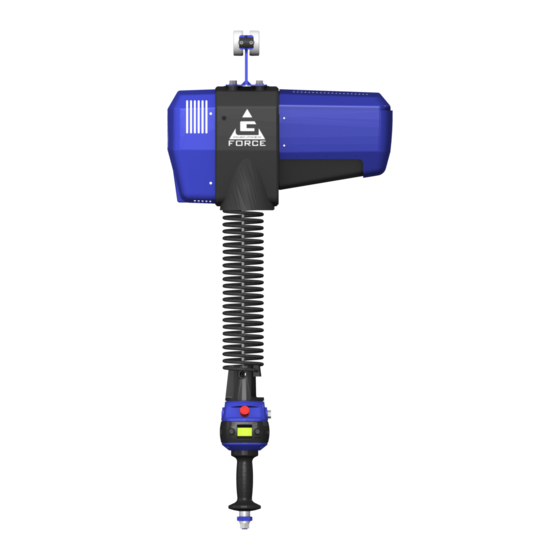
Page 8: G-Force® Main Assembly Component Description
Always have this serial number available during all correspondence regarding your G-Force or when ordering repair parts. WARNING Do not field modify the G-Force in any way. Any modification, without the written consent of Gorbel Inc, will void warranty. -
Page 9: Installation
Carefully remove all items from the box. Verify that all components listed on the packing slip are included. If any items are missing or were damaged during shipping, please contact Gorbel® Inside Sales or After the Sales Service (ATSS) immediately at (800) 821-0086 or (585) 924- 6262. -
Page 10: Step 4 - Coil Cord Installation
STEP 4 - COIL CORD INSTALLATION TIP: This step is best completed once the actuator has been installed into the bridge system. Note: G-Force® units, standard in-line or remote mounted, that are ordered from the factory will be shipped with the coil cord assembled to the actuator wear ring and the coil cord footer, creating the coil cord assembly (diagrams 4A and 4B). -
Page 11: Step 5A - In-Line Slide & Force Sensing Slide Handle Installation
STEP 5A - IN-LINE SLIDE & IN-LINE FORCE SENSING HANDLE INSTALLATION Wire Rope Coil Cord Footer 5A.1 Ensure the wire rope is still fed through the center of the coil cord. Hold the slide handle just below 16 mm Shoulder Bolt the coil cord. - Page 12 STEP 5B - REMOTE MOUNTED SLIDE HANDLE INSTALLATION (CONTINUED) 5B.4 Once the wire rope, coil cord footer and G360™ swivel are aligned, replace the 16mm shoulder bolt thereby capturing the wire rope, coil cord footer and G360™ swivel (diagram 5B1, page 12). 5B.5 Thread the coil cord connector into the G360™...
-
Page 13: Step 5C - Suspended Pendant Handle Installation
STEP 5C - SUSPENDED PENDANT HANDLE INSTALLATION 5C.1 Assure that the coils of the pendant handle coil cord are centered around the pendant handle wire rope. 5C.2 Remove the eyebolt from suspended pendant cable assembly using the threaded connector. 5C.3 Thread the eyebolt into the bottom of the actuator Eyebolt With Hexnut assembly as shown (diagram 5C1). -
Page 14: Step 5D - Remote Mounted Pendant Handle Installation
STEP 5D - REMOTE MOUNTED PENDANT HANDLE INSTALLATION (CONTINUED) Wire Rope 5D.4 Once the wire rope, coil cord footer and G360™ swivel are aligned, replace the Coil Cord Footer 16mm shoulder bolt thereby capturing the wire rope, coil cord footer and 16 mm Shoulder Bolt G360™... -
Page 15: Step 5E - 1320 Lb. In-Line Slide Or Remote Mounted Handle Installation
STEP 5E - 1320 LB. INLINE SLIDE & REMOTE MOUNTED HANDLE INSTALLATION 5E.1 With the actuator hanging from the rail or other supported structure, thread the free end of the wire rope through the coil cord assembly so it hangs below the coil cord mounting plate and attach the wear ring to the wear ring bracket (inside actuator wire rope opening), using the supplied hardware (diagram 5E1). -
Page 16: Step 5F - 1320 Lb. Suspended Pendant Handle Installation
STEP 5F - 1320 LB. SUSPENDED PENDANT HANDLE INSTALLATION 5F.1 With the actuator hanging from the rail or other 4X 65018 support structure, thread the free end of the wire 4X 65052 rope through the coil cord assembly, so it hangs below the coil cord mounting plate and attach the 83255 (PULLEY) 83261 (BEARING) -
Page 17: Step 5G - 1320 Lb. Air Hose Installation (Option)
STEP 5G - 1320 LB. AIR HOSE ASSEMBLY INSTALLATION (OPTIONAL) 5G.1 The air hose assembly comes attached to the wear ring and coil cord mounting plate. Once the handle installation is complete, the air hose should be installed. 5G.2 Remove two of the screws and lockwashers holding the reinforcement plate to the underside of the actuator (leaving the spacers in place) and insert them through the air hose bracket and reattach to the underside of the actuator. -
Page 18: Step 5H - Remote Mount Force Sensing Slide Handle Installation
STEP 5H - REMOTE MOUNT FORCE SENSING SLIDE HANDLE INSTALLATION 5H.1 Follow Steps 5B.1 through 5B.7 on pages 12 and 13 to install G360™. 5H.2 Bracket must be sized to fit the handle it will be holding and rigid enough to resist the forces exerted on it (diagram 5H1). -
Page 19: Step 5I - Remote Mount Force Sensing Hub Handle Installation
STEP 5I - REMOTE MOUNT FORCE SENSING HUB HANDLE INSTALLATION WARNING This handle is only intended for remote mount applications and must not be used for transmitting lifting loads. 5I.1 Follow Steps 5B.1 through 5B.7 on pages 12 and 13 to install G360™. 5I.2 Mount Hub body to tooling rigidly to resist forces exerted on it. -
Page 20: Step 6 - Electrical Power Connection
Finally, test the operation of any special tooling that may have been integrated to the G-Force®. TIP: Gorbel, Inc., does not provide integrated tooling for the G-Force®. All tooling related questions should be directed to the tooling manufacturer or supplier. -
Page 21: Step
STEP 8 - FLOAT MODE TIP: Gorbel® Inside Sales is available from 7am to 6pm Eastern Time Monday - Thursday and 7am to 5pm Eastern Time Friday. Float Mode may be activated by simply pressing the G-Force® logo button on the left-hand side of the handle (diagram 8A). - Page 22 See page for mechanical adjustment should the need arise due to tooling changes, wear, etc. Please contact Gorbel® After the Sales Service department (585-924-6262) if any of the following occur. DO NOT ATTEMPT TO REPAIR UNIT YOURSELF. •...
-
Page 23: Step 9 - Expansion I/O Block Mounting Instructions (Option)
TIP: Expansion I/O block mounting instructions only apply to iQ2 units with an I/O block. STEP 10 - EXPANSION I/O BLOCK MOUNTING INSTRUCTIONS (OPTION) DIMENSIONS Diagram 10A. Expansion I/O block dimensions (millimeters). Diagram 10B. Screw fastener drilling template. -
Page 24: Lift Functionality
Standard Operation - Force Sensing Hub Handle: Handlebars (Gorbel® optional kit 74630, or by others) are attached to a mounting plate which in turn is connected to a force sensing device so that when the user applies a vertical force up or down, this is interpreted as intent to move. Speed of the unit is proportional to the amount of force applied. - Page 25 LIFT FUNCTIONALITY (CONTINUED) Program Mode: In this mode, the operator can control speed, acceleration, service features and other variable settings OLED DISPLAY EMERGENCY STOP BUTTON (diagram B or C). See the Program Mode section, page 25, for complete programming POTENTIOMETER functionality located at the handle.
- Page 26 The handle operates exactly the same as if it were mounted in-line. The end user must supply Gorbel® with the required length of the extension cable such that it can be safely routed and clamped to the tooling.
-
Page 27: Controls Interface Features
CONTROLS INTERFACE FEATURES The jog switch push buttons and communica- tions connector are protected by a cover (diagram E). To access the jog switch push buttons and communications connector, loosen the M4 nut and slide the shield back towards the wire rope. Note: Do not fully unthread the M4 nut. -
Page 28: Program Mode
PROGRAM MODE Overview (Software Version R2.0) Program Mode is used to control and adjust all of the features on the Q2 and iQ2 series G-Force®. Before entering Program Mode, review the Program Mode Menu outline, Chart D, pages 30-35. Note: An alternative to using Programming Mode via the Handle is the HMI Visualization which can be accessed via a PC with a VNC Viewer installed. - Page 29 PROGRAM MODE (CONTINUED) Handle Operation Avoid the OPS: Make sure to keep fingers clear of the photo sensor area when in program mode. Breaking the photo sensor will drop the unit out of program mode and you will need to start over again.
-
Page 30: Menu And Sub-Menu Selections
Gorbel® Recommends: The minimum distance between any two virtual limits to be no less than two (2) inches for best performance and user experience. Please note this distance is greatly dependent on Unit Speed, Responsiveness, Capacity, and Load, individual results may vary. - Page 31 Overview: Configure the lifting responsiveness or the acceleration setting. CURRENT XXX Displays the current response setting. Read-Only (Medium by default) RESPONSE The handle control response options are defined as follows: MEDIUM Response Low = 75% of the maximum responsiveness HIGH setting Medium = 85% of the maximum responsiveness setting...
- Page 32 Settings FLOAT FLOAT TO OVER Over-Force Detection: Unit terminates Float Mode if user’s operating force exceeds the MODE SUB MODE FORCE/SPEED maximum force limit or a dropped weight is MENU ANTI- detected by evaluating the force profile. RECOIL Different from Over-Speed Detection, unit can run at the maximum Float Mode speed.
- Page 33 Menu Feature Description Group Name Sub-Group/ Parameter Value Navigation Name Settings FLOAT FLOAT MODE Float Mode Gain Selection Sub-Menu. '-DOES Selections from Lowest which is the least MODE SUB GAINS responsive but most stable, to High which is MENU APPLY the most responsive and least stable.
- Page 34 Menu Group Name Sub-Group/ Parameter Feature Description Value Name Navigation USER CHANGE TO LEVEL X Set Overload Detection Sensitivity to between 5 (HIGH) and 1 (LOW) one level decrements OVERLOAD SENSITIVITY at a time. By default, the sensitivity is set at 5. SUB MENU RETURN BACK TO Return back to the Settings selection...
- Page 35 PROGRAM MODE (CONTINUED) Lockout Feature (chart B) To prevent tampering in Program Mode, a Lockout Feature is available. To Lockout Program Mode from the Handle: Chart A. Program Mode Process 1. Press both the G-Force® logo button and the MENU button simultaneously for five seconds.
- Page 36 PROGRAM MODE (CONTINUED) Safety Program Mode If the G-Force® has detected a fault or is running in SERVICE MODE, only a limited set of menus are accessible. For example, if the G-Force® records a fault, when Program Mode is activated the OLED will display LIMITED PRG MODE rather than PROGRAM MODE.
- Page 37 PROGRAM MODE (CONTINUED) Feature Description Program Mode Menu OLED Text UPPER Keep the load at the desired position and select to set the upper limit. LIMIT Keep the load at the desired position and select to set the lower limit. Virtual Limits LOWER Note: Setting the upper and lower virtual limits to the same position will cause the...
- Page 38 PROGRAM MODE (CONTINUED) Program Mode Menu OLED Text Feature Description FM Setup Startup prompt screen when this sub-menu is accessed. Menu ENABLE Enable or Disable running Float Mode related features, such as Standard Float DISABLE Mode, Remote-Mount Float Mode Trigger, Dual Float Mode Weights, etc. FLOAT MO [SUB-MENU] FM ANTI-...
- Page 39 PROGRAM MODE (CONTINUED) Program Mode Menu OLED Text Feature Description USER Startup prompt screen when this sub-menu is accessed. Please activate weight readout while setting an overload limit, to ensure that the load cell is properly SUB-MENU calibrated and the desired overload limit is within the acceptable range. Please see WEIGHT READ ON_ under SETTINGS MENU for additional details.
- Page 40 Digital Input). More virtual limit sets are possible to configure via the visualization or with custom programming. Gorbel® recommends the minimum distance between any two virtual limits to be no less than 2 inches for best performance and user experience.
- Page 41 PROGRAM MODE (CONTINUED) Tip: I/O Functionality may be assigned via HMI Visualization programming to meet application requirements. Review the HMI Visualization Programming Appendix for more options and details. iQ2 Actuator Programmable Input/Output Module Functionality Assigned Function Description Point Input - Dual virtual When this input option is turned on, the G-Force switches to a second ®...
- Page 42 PROGRAM MODE (CONTINUED) Tip: I/O Functionality may be assigned via HMI Visualization programming to meet application requirements. Review the HMI Visualization Programming Appendix for more options and details. iQ2 Expansion Programmable 8-Point Input/Output Block Functionality Assigned Description Settings (see chart A for instructions on Point Function navigating and setting menu functions)
- Page 43 PROGRAM MODE (CONTINUED) Tip: I/O Functionality may be assigned via HMI Visualization programming to meet application requirements. Review the HMI Visualization Programming Appendix for more options and details. Q2 Handle Programmable Input/Output Functionality Assigned Function Description Point Input – Inhibit Motion 1…...
- Page 44 PROGRAM MODE (CONTINUED)
- Page 45 PROGRAM MODE (CONTINUED) lwER R·1_ ll i::.:. ®...
- Page 46 PROGRAM MODE (CONTINUED)
-
Page 47: Troubleshooting
TROUBLESHOOTING Failure Possible Solution There is no display on • Verify the correct AC power to the actuator. the OLED screen on the • Check the coil cord connections at both the handle and actuator. handle. • Check the overall condition of the coil cord. Look for broken or exposed wiring. •... - Page 48 It is also possible that the fault clearance may require a more specific corrective action, such as replacing the wire rope, checking certain external input/ output modules or some other service-related task. If necessary, check with your Gorbel® distributor or contact Gorbel® After the Sales Service (ATSS) at 800-821-0086 for assistance.
-
Page 49: Led Status Chart
TROUBLESHOOTING (CONTINUED) LED Chart: The chart below shows the status of the LED lights in different states. Machine State Sub-State (if applicable) Color OLED TEXT E-Stop Engaged No Light E-STOP ENGAGED Programming Mode Amber PROGRAMMING MODE COMMAND FAULT PLC (Command) Fault Flashing Red ERROR NUMBER: ####... -
Page 50: Technical Specifications
TECHNICAL SPECIFICATIONS G-Force® Q2 & iQ2 Actuator 165 lb 330 lb 660 lb 1320 lb Max Capacity [kg] [75kg] [150kg] [300kg] [600kg] Max Lift Speed ft/min 195 fpm 95 fpm 45 fpm 25 fpm Unloaded [m/min] [59 mpm] [29 mpm] [14 mpm] [8 mpm] Max Lift Speed... -
Page 51: Wire Rope Inspection, Maintenance, & Replacement
WIRE ROPE INSPECTION 1. Frequent Inspection The operator or other designated person should visually inspect all ropes at the start of each shift. These visual observations should be concerned with discovering gross damage, such as listed below, which may be an immediate hazard: •... - Page 52 CAUTION Rope should be maintained in a well-lubricated condition. Gorbel recommends using chain and cable penetrating oil for lubrication. Lubricant applied as part of a maintenance program shall be compatible with the original lubricant (PreLube 6). Lubricant applied shall be of the type that does not hinder visual inspection.
- Page 53 WIRE ROPE REPLACEMENT INSTRUCTIONS WARNING Wire rope replacement is to be performed by qualified maintenance personnel only. Removal of Existing Wire Rope: 1. Make sure the replacement rope is the same length and diameter (3/16” or ¼”) as rope currently on actuator unit.
- Page 54 WIRE ROPE REPLACEMENT INSTRUCTIONS (CONTINUED) Removal of Existing Wire Rope (Continued): 9. From the limit switches is a gray colored 6 conductor lead that plugs into the circuit board. Its connected location is approximately two inches down the right side of the circuit board labeled “limits”. Gently press in the locking tab and pull out the plug lead to disconnect plug from board (diagram O).
- Page 55 WIRE ROPE REPLACEMENT INSTRUCTIONS (CONTINUED) Removal of Existing Wire Rope (Continued): From the limit switches is a gray colored lead that plugs into the circuit Limit Switch board. Its connected location is approximately two inches down the right Limit Switch Plug side of the circuit board labeled “limits”.
- Page 56 WIRE ROPE REPLACEMENT INSTRUCTION (CONTINUED) Installation of New Wire Rope: 1. Grasp anchor end of rope (not thimble) and make a crimp in gloved hand approximately three inches from the end (try to kink rope to make a bend radius). 2.
- Page 57 1320 LB. WIRE ROPE REPLACEMENT INSTRUCTIONS 1. Disconnect handle or G360™ from wire rope by disconnecting coil cord and/or air hose (if applicable), removing coil cord mounting plate, and removing pulley pin. 2. Remove fasteners holding the reinforcement plate to the bottom of the actuator and nuts holding the U-bolt, freeing the end of the wire rope.
-
Page 58: Slack Spring Adjustment
SLACK SPRING ADJUSTMENT Slack spring adjustment is necessary if one or more of the following conditions apply: • When wire rope continues to “pay out” from actuator when end effector (handle, tooling) is being supported and down travel is commanded. •... -
Page 59: Recommended Spare Parts Kits
To order any of these kits, please contact your authorized Gorbel® distributor. You will have to know your system specifications such as Serial Number, Capacity, Trolley Saddle Height, Height Under Hook and Span (if applicable to your unit). -
Page 60: Dual Handle Setup Instructions
220VAC Power Supply to the G-Force®. Two handles (Slide and/or Pendant ONLY). • • Tools depend on Handle type, contact Gorbel® After the Sales Service for more info disassembling the Handle. 4. Procedure 5.1 Setting up Handle Configurations: Disconnect BOTH handles from the Actuator. - Page 61 DUAL HANDLE SETUP INSTRUCTIONS (CONTINUED) NOTE: When Switch 1 is in the OFF position, the Handle is at Node 10 and active. When Switch 4 is in the ON position, the Handle CAN communication is terminated. Switch Handle 1 Handle 2 5.2 Setting up Handle Connections •...
-
Page 62: G-Force® Hmi Visualization
Configuration is as follows (See Appendix F for instructions to set-up): 6. IPv4 Address: 192.168.105.99 1. Subnet Mask: 255.255.255.0 7. Need a VNC Viewer Program? Gorbel® recommends the B&R VNC Viewer (See Appendix B for instructions to install). 8. 5.2 HMI Visualization Hierarchy Gorbel’s G-Force®... - Page 63 5.3 VNC PAGES OVERVIEW Page Sub Page Content User Log In Page Management Calibrate Factory Settings Factory Test Manual Control Page Manual Configuration System Config Import/Export Config IP Address settings Set Actuator I/O, standard presets and clear all previous Actuator settings I/O Config I/O &...
- Page 64 This read-only field will show the IP Address of the Actuator. Reset Password Optionally update the password to something more secure. Note: If the password is lost please contact Gorbel® After the Sales Service for instructions to reset. Login as Admin by Default Check this box to login as admin by default.
- Page 65 5.4.2 SYSTEM CONFIG PAGE Feature Description Manual Configuration Serial Number The serial number is populated by CraneBrain®. I/O Type This automatically detects the I/O type of the unit Type G-Force® or Easy Arm®. Span If Easy Arm®, span can be selected. Capacity Capacity of the unit.
- Page 66 Import from Selected Once multiple .xml files are made, scroll using the arrow buttons to choose one to import back to the Actuator. Export to Selected To change the configuration of a .xml file, set the configuration desired from the Manual Configuration section, scroll using the arrow buttons to choose the .xml file to overwrite, and then press Export to Selected.
- Page 67 5.4.3 IO CONFIG PAGE Feature Description Actuator I/O The Actuator I/O will come with 8 inputs and 4 outputs. iQ2 units will have Actuator I/O and/or an I/O Block. Q2 units will have Handle I/O to configure. Inputs AD Clamp Anti-Drop Clamp input signal.
- Page 68 Unclamp signal Input does not trigger the unclamp output when lifting a weight, thereby protecting a weight from being dropped. Setting Anti-Drop Tool weight: To use the Anti Drop Clamp and Unclamp inputs and outputs, navigate to the Advanced Settings Tab on the settings page, and click on set adjacent to Anti-Drop Tool Weight, when the only the tool is being lifted by the system.
- Page 69 Jog Up This is a maintained input, and when it’s ON it jogs up based on the set Custom Up Jog speed Jog Down This is a maintained input, and when it’s ON it jogs down based on the set Custom Down Jog speed Setting Custom Jog Speed: To set jog speed, navigate to the Speed Menu Tab on the Settings page, and click on + (to add 5%) or ++ (to add 10%) (Vice Versa for –...
- Page 70 Fault Indicator If there is a fault (error) in the unit, this output turns on. Service Indicator If the service duration that is set is reached, the output turns ON. Setting Service Warning: To set the Service Warning, navigate to the Service Menu Tab on the Settings page.
- Page 71 5.4.4 IO CONFIG PAGE (Expansion Block and Handle IO) Feature Description Expansion Block I/O The Expansion Block I/O will come with 8 configurable I/O points (toggle between states [input or output] by clicking the word “Input” or “Output” next to each I/O). This set of input and output features will be identical to Actuator I/O.
- Page 72 5.4.5 PROGRAM MENU PAGE (VIRTUAL LIMITS) Feature Description Virtual Limits The difference between setting and enabling is that ‘set’ saves the hoist position, while ‘enable’ activates the virtual limit. Number This number is for choosing the set of virtual limits you’re trying to set (max is 4) Upper Limit Program the upper virtual limit (load must be at desired position for upper limit).
- Page 73 5.4.6 PROGRAM MENU PAGE (SPEED) Feature Description Toggle speed This is regarding the Toggle Speed Input selection. If that input is on, the unit changes speeds to this set speed. If the input is off, it goes back to hoist speed selected. Custom Jog Speed This is regarding the Custom Jog Input selection.
- Page 74 5.4.7 PROGRAM MENU PAGE (RESPONSE) Feature Description Handle Set the lowest handle control response corresponding to about 75% of the highest responsiveness setting. Set the medium handle control response corresponding to about 85% of the highest responsiveness setting. High Set the highest handle control responsiveness setting. Float Lowest (least responsive / most stable) Float Mode gains.
- Page 75 5.4.8 PROGRAM MENU PAGE (SETTINGS) Feature Description Weight Display Zero Zero the weight display. On/Off Turns the weight display ON/OFF on the OLED. kg/Lbs. Sets the units of the weight display, separately from the Unit Select configuration. Idle Timeout Select Choose which idle time to configure.
- Page 76 Unload Stop Optional feature utilizing Anti-Recoil detection. When user sets a weight onto a surface in Float Mode, it is terminated if Anti-Recoil detects an unloading. This can be useful for applications needing a quick Float Mode exit to an idle state to allow user to work on the part. Note: As a result of the extra detection, Float Mode is likely to terminate when the upper limit switch is hit while unit is running at a fast speed.
- Page 77 5.4.9 PROGRAM MENU PAGE (ADVANCED SETTINGS) Feature Multiple FM Tool Weight Program the feature by clicking Set at the desired value shown in the “Value” column. NOTE: Works when Dual Float Input is enabled Multiple FM Load Weight Program the feature by clicking Set at the desired value shown in the “Value”...
- Page 78 5.4.10 PROGRAM MENU PAGE (SERVICE MENU) Feature Description Operating Cycle Upper (Set) Set the upper hoist position for cycles. Lower (Set) Set the lower hoist position for cycles. Zero Zero the variable (for counts, slowdown, loaded, unloaded…etc) Counts This increments when a cycle is completed between the Upper and Lower sets.
- Page 79 5.4.10 PROGRAM MENU PAGE (SERVICE MENU - DIAGNOSTICS) Feature Description Diagnostics Page Handle Lights indicate when handle options are triggered, and Analog indicates the current value of the analog control signal in counts. Hoist Lights indicate if the Upper / Lower limit or Slack switches are triggered.
- Page 80 5.4.11 PROGRAM MENU PAGE (FAULT LOG) Feature Description Command Faults & Warnings The upper pane shows the most recent 20 Command Faults & Warnings. Drive Faults The lower pane shows the most recent 20 Drive Faults. Refresh Log Updates the log list with any new or active errors.
-
Page 81: Appendix A: Ap Field Customization Instructions
Gorbel Operating Procedure Appendix A – AP Field Customizations Instructions Purpose This procedure describes steps to customize the settings on the Access Point (AP) on the G-Force® Q2 and iQ2 products. Scope This procedure applies to both Q2 and iQ2 G-Force® and Easy-Arm products. - Page 82 Subnet Mask: 255.255.255.0 Login to the AP: Open a web browser and connect to 192.168.105.1 and login using the ‘Order Number’ in the Passphrase field. Figure 2: Login NOTE: Screen If the Passphrase is forgotten or does not work (“Order Number”, “mypassword” or any other custom password set by the end user).
- Page 83 1. Transmit Power/Channel Instructions: If there are multiple G-Forces with configured APs in near proximity the Transmit Power Setting can be reduced to just strong enough, so it does not impede connecting to other units. (This may require a shorter distance between the PC and the G-Force®...
-
Page 84: Appendix B: Ap Vnc Viewer Install Instructions
Tools Used: Laptop with WiFi connectivity. Access Point VNC Viewer Install Instructions Download: the suggested VNC viewer is the B&R VNC Viewer (Supported by Gorbel®) or use the VNC Viewer of your choice. Click Here! to automatically begin the download. - Page 85 Figure 9: VNC Viewer App...
-
Page 86: Appendix C: Ap Connection Quickstart Guide
Gorbel Operating Procedure Appendix C - AP Connection QuickStart Guide 5. Purpose This procedure describes steps to connect and access the HMI on the G-Force® Q2 and iQ2 products. 6. Scope This procedure applies to both Q2 and iQ2 G-Force® and Easy-Arm products. - Page 87 Subnet Mask: 255.255.255.0 2. Open VNC Viewer Application: Open a VNC viewer program on your PC. Need a VNC Viewer Program? Gorbel® supports the B&R VNC Viewer (See Appendix B for instructions to install) 3. Specify G-Force® IP Address: The VNC viewer needs the G- Force®...
-
Page 88: Appendix F: Pc Ip Address Set Up For Wired Connections
Gorbel Operating Procedure Appendix F - PC IP Address Setup for Wired Connections 9. Purpose This procedure describes steps to setup the Computer’s IP Address so that either the WiFi Access Point (AP) on the G- Force® actuator board can be configured or so that the PC can directly connect to the Actuator CPU. - Page 89 Figure 11: Ethernet Settings Double click on Ethernet to open the Ethernet Properties, and double click on Internet Protocol Version 4 (TCP/IPv4) to open General IP settings (Ref: Fig 3) Figure 12: Internet Protocol Settings • Apply the following settings and then click OK and OK again to apply it to the Ethernet port previously selected (Ref: Fig 4) IPv4 Address: 192.168.105.99 •...
-
Page 90: Limited Warranty
Cancellations: If it becomes necessary for the purchaser to cancel this order wholly or in part, he shall at once so advise Gorbel in writing. Upon receipt of such written notice all work will stop immediately. If the order entails only stock items, a flat restocking charge of 15% of the purchase price will become due and payable by Purchaser to Gorbel. -
Page 91: Ce Declaration Of Conformity
CE Declaration of Conformity Hereby, Gorbel Inc., declares that this material handling equipment is in compliance with the essential requirements and other relevant provisions listed below. EMC Directive: 2014/30/EU Emissions Testing for EN 61000-6-4:2007+A1:2011 Industrial Environments: ISM Radio Frequency EN 55011:2009+A1:2010... -
Page 92: Inspection And Maintenance Schedule
Fishers, NY 14453-0593 For additional service information, please consult the G-Force® Q2 and iQ2 Phone: (800) 821-0086 Fax: (800) 828-1808 Series Service Manual. Contact the Gorbel® After the Sales Service group to E-Mail: info@gorbel.com request a copy. http://www.gorbel.com © 2020 Gorbel Inc.
Need help?
Do you have a question about the G-Force Q2 Series and is the answer not in the manual?
Questions and answers