Sign In
Upload
Manuals
Brands
golmar Manuals
Intercom System
NEXA Series
User Manuals: golmar NEXA Series Video intercom system
Manuals and User Guides for golmar NEXA Series Video intercom system. We have
1
golmar NEXA Series Video intercom system manual available for free PDF download: User Manual
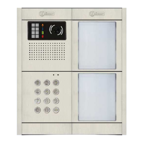
golmar NEXA Series User Manual (146 pages)
Audio and Video Door Entry System
Brand:
golmar
| Category:
Intercom System
| Size: 9 MB
Table of Contents
Table of Contents
6
Contents
6
Characteristics
6
Door Panel Installation
7
Location of the Embedding Box
7
Panel
7
Positioning the Embedding Box
7
Description of the Module
8
Description of the Beeps
8
Description of the JP1 Jumper
8
Description of the N3301/AL - NX3301 Module
8
Description of the SW1 DIP Switch
8
Description of the Self-Testing LEDS
9
Power Supply Unit Installation
9
Detail of the TF-104 Power Supply Unit Installation
9
Lock Release Installation
9
Module Operation
10
Description of Module Operation
10
Module Programming
11
Programming Mode Entry and Exit
11
Programming Mode Structure and Sequence
11
Programming Fields
12
Factory Setting
21
Wiring Diagrams
22
Access Control with Call Buttons
23
Audio and Video Door Entry System - Access Control
24
Characteristics
24
Description of the Nexa Modular Door Panel
26
Description of the Sound Modules
27
Description of the EL655 Sound Module
27
Description of the EL651 Sound Module
28
Description of the EL620/2PLUS Sound Module
29
Description of the Self-Testing Leds
30
Description of the SW1 DIP Switch
30
Description of the EL632 PLUS P/T - EL642/PLUS Sound Module
31
Description of the SW1 - SW2 DIP Switch
32
Binary Coding of the SW2 DIP Switch
33
Description of the CN8 Nexa Bus Link Connector
33
Description of the CN3 Function Connector
34
Description of the EL632 R5
35
Description of the CN7 Nexa Bus Link Connector
36
Description of the SW1 DIP Switch
36
Description of the Button Modules
37
Description of the EL610A Button Module
37
Description of the EL610D Button Module
38
Description of the N3301/AL - NX3301 Access Control Module
39
Description of the JP1 Jumper
40
Description of the S Elf-Testing Leds
40
Description of the SW1 DIP Switch
40
Description of the Beeps
41
Installation of the Door Panel
41
Location of the Embedding Box
41
Mounting the Electronic Modules
42
Preparing the Cable Entry and Fitting the Embedding Box
42
Cabling, Connection and Button Configuration
43
Closing the Door Panel
43
Fastening the Frame to the Embedding Box
43
Final Adjustments
43
Description of Door Panel Operation
44
Installation of the FA-PLUS and FA-PLUS/C Power Supply
44
Installation of the Lock Release
44
Programming the Door Panel
44
Programming the Tekna Plus SE Monitors
45
Programming Tekna R5 Col SU-R5 Monitors
47
Programming T-540 Plus SE Telephones
48
Programming T-530 R5 SU R5 te Lephones
50
Wiring Diagrams
51
Contents
24
Coded Door Panel
54
Audio and Video Door Entry System - Coded Door Panel
55
Characteristics
55
Contents
55
Description of the Nexa Modular Door Panel
57
Description of the Sound Module
58
Description of the EL632 PLUS P/T - EL642 PLUS Sound Module
58
Binary Coding of the SW2 DIP Switch
60
Description of the CN8 Nexa Bus Link Connector
60
Description of the SW1 - SW2 DIP Switch
60
Description of the CN3 Function Connector
61
Description of the EL632 R5 P/T - EL642 R5 Sound Module
62
Description of the CN7 Nexa Bus Link Connector
63
Description of the SW1 DIP Switch
63
Description of the EL632 GTWIN
64
Description of the SW1 DIP Switch
65
Description of the SW2 DIP Switch
65
Description of the CN Nexa Bus Link Connector 8
66
Description of the SW3 - SW4 Rotary Switch
66
Description of the N3301/AL - NX3301 Coded Module
67
Description of the JP1 Jumper, SW1 DIP Switch and Self-Testing Leds
68
Description of the Beeps
69
Installation of the Door Panel
69
Location of the Embedding Box
69
Fastening the Frame to the Embedding Box
71
Connection of the Nexa Bus between the Sound Module and the Coded Module
71
Closing the Door Panel
72
Installation of the FA-PLUS FA-PLUS/C , and FA-GTWIN Power Supply Unit
72
Installation of the Lock Release
72
Description of Door Panel Operation
73
Programming the Door Panel (Entry, Exit, Programming Structure and Sequence)
74
Programming Fields
75
Factory Setting
84
Programming Tekna Plus SE Monitor
86
Programming Tekna R5
87
Col SU-R5 Monitors
87
Programming (Tekna Gtwin/ Tekna-HF Gtwin and Tekna -S Gtwin) Monitors and T-5924 Gtwin Telephones
88
Programming T-540 Plus SE Telephones
90
Programming T-530 R5
92
SU-R5 Telephones
92
Wiring Diagrams
93
Contents/Characteristics
99
Characteristics
99
Contents
99
Coded Panel with Display
100
Description of the Nexa Modular Door Panel
100
Description of the Sound Modules
102
Description of the EL632 PLUS P/T - EL642/PLUS Sound Module
102
Description of the CN8 Nexa Bus Link Connector
103
Description of the SW1 - SW2 DIP Switch
103
Description of the CN3 Function Connector
104
Description of the EL632 R5 P/T - EL642/R5 Sound Module
105
Description of the CN7 Nexa Bus Link Connector
106
Description of the SW1 DIP Switch
106
Description of the EL632 GTWIN Sound Module
107
Description of the CN8 Nexa Bus Link Connector
108
Description of the SW1 DIP Switch
108
Description of the SW2 DIP Switch
108
Description of the SW3 & SW4 Rotary Switch
108
Description of the N3301/AL - NX3301 Coded Module
109
Description of the JP1 Jumper, SW1 DIP Switch, Self-Diagnostic Leds and Beeps
110
Description of the N3403/AL - NX3403 Display Modules
111
Description DIP Switch
111
Description of the Nexa Bus Link Connector
112
Description of the USB Connection LED Indicator
112
Description of the USB Connector
112
Installation of the Door Panel
112
Location on the Embedding Box
112
Preparing the Cable Entry, Fitting the Embedding Box and Mounting the Electronic Modules
113
Fastening the Frame to the Embedding Box
114
Nexa Bus Connection
114
Closing the Door Panel
115
Installation FA-PLUS, FA-PLUS/C & FA-GTWIN Power Supply Unit
115
Installation of the Lock Release
115
Description of the Door Panel Operation
116
Programming the Door Panel
117
Configuartion Menu and Programming Entry and Exit
117
System Settings Menu
118
Automatic Programming Mode for Monitors and Telephones (Plus y Vista Plus)
124
Access Control Menu
125
Residents List Menu
130
Editing with the Keypad
134
Programming the Tekna Plus SE Monitors
135
Programming the Tekna R5 Col SU-R5 Monitors
136
Programming the Gtwin Monitors and Telephones
137
Programming the T-540/Plus SE Telephones
139
Programming the T-530 R5 SU-R5 Telephones
139
Wiring Diagrams
141
Advertisement
Advertisement
Related Products
golmar Nexa Modular
golmar Nexa 90
golmar NHEA PLUS SE TERMINAL
golmar Nexa
golmar NHEA GB2
golmar 0111
golmar 12210705
golmar 12226502
golmar 12226512
golmar Categories
Intercom System
Monitor
Telephone
IP Access Controllers
Relays
More golmar Manuals
Login
Sign In
OR
Sign in with Facebook
Sign in with Google
Upload manual
Upload from disk
Upload from URL