Sign In
Upload
Manuals
Brands
Global Manuals
Portable Generator
MX PrimeGen
User Manuals: Global MX PrimeGen Power Generator
Manuals and User Guides for Global MX PrimeGen Power Generator. We have
2
Global MX PrimeGen Power Generator manuals available for free PDF download: Installation, Operation And Maintenance Manual, Service And Maintenance Manual
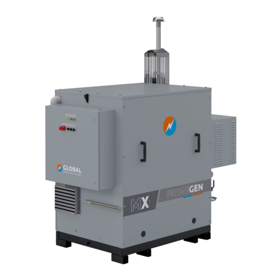
Global MX PrimeGen Installation, Operation And Maintenance Manual (71 pages)
Power Generator
Brand:
Global
| Category:
Portable Generator
| Size: 3 MB
Table of Contents
Table of Contents
3
Copyright, Liability, and Contact Information
7
Important Safety Instructions
8
Manual Icons and Safety Banners
10
Technically Qualified Personnel
10
Battery Safety
10
Start-Stop Operations
11
Product Information
12
Terms and Acronyms
13
Data Plate
14
Figure 3-1 - Data Plate
14
Figure 3-2 - MX Model Tree
14
Assembly and Installation
15
Site Preparation
15
Location and Access
15
Figure 4-1- Anchor Hole Layout
15
Fuel Supply
16
Standard Specifications for Gaseous Fuel
16
Unpacking and Lifting
17
Table 1 - MX Power Generator Fuel Specifications
17
Figure 4-2 - Slinging and Lifting Diagram
18
Figure 4-3 - Lifting with Forklift
18
Access Panels
19
Figure 4-4 - Location of Access Panel Fasteners
19
Assembly and Installation
20
Figure 4-5 - Assembly
20
Batteries
21
Figure 4-6 - Batteries and Connectors
21
Radiator Glycol
22
Figure 4-7 - Battery Wiring Terminations
22
Fuel Supply
23
Wiring Connections
23
Figure 4-8 - Location of Coolant Reservoir and Expansion Tank
23
Figure 4-9 - Holes for Customer Connections
24
Figure 4-10 - Customer Wiring Terminations (Single Phase Systems)
24
Figure 4-11 - Customer Terminations (3 Phase Systems)
25
Table 2 - Customer Wiring Connections (Single Phase Systems)
25
Wind Shield Adjustment
26
Figure 4-12 - Wind Shield Recommended Gap from Radiator Shroud Cover
26
Table 3 - Customer Wiring Connections (3 Phase Systems)
26
Start-Up
27
Local Start-Up
27
Figure 5-1 - Operation Switches
27
Figure 5-2 - Main System and Battery Charger Breakers (Single Phase)
27
External Battery Charge and Cold Ambient Start
28
Figure 5-3 - Breakers Located Inside the Electrical Panel Enclosure (Single Phase)
28
Figure 5-4 - Breakers Located Inside the Electrical Panel Enclosure (3 Phase)
28
Figure 5-5 - Main System and Battery Charge Breaker (3 Phase)
28
Remote Start-Up
29
Operation
30
User Interface Settings
30
Esd Button
30
Loc/Rem Switch - Local / Remote Modes
30
Figure 6-1 - Operation Switches
30
Auto/Man Switch - Auto-Standby / Manual Modes
31
Local On/Off
32
Led Status Lights
32
Start and Stop Buttons
32
Led Display
32
Figure 6-2 - Alternate Pump Button Location
32
Display Screens
33
Figure 6-3 - LED Display
33
Remote Monitoring
38
Remote Monitoring through Dry Contacts (Scada)
38
Remote Monitoring through Modbus
39
Table 4 - MX Modbus Configuration Settings
39
Table 5 - MX Generator Modbus Map
40
Remote Monitoring through Iot
42
Log-In Instructions
42
Figure 7-1 - Cellular Modem Located in the Electrical Enclosure
42
Figure 7-2 - Log-In Page for Remote Monitoring System
43
Figure 7-3 - Remote Monitoring System Dashboard
44
Shutdown
45
Emergency Shutdown (Esd)
45
Service and Maintenance
47
Recommended Maintenance and Intervals
47
Standby Oil Systems
48
Table 6 - Maintenance Schedule for Standby Oil Systems
48
Systems with Extended Oil Reservoir
49
Table 7 - Maintenance Schedule for Systems with Extended Oil Reservoir
49
System Check
50
System Shutdown and Lock out for Maintenance
50
Fuel Train Assembly Leak Check
50
Air System Filters Check
51
Figure 9-1 - Engine Air Intake Figure 9-2 - Engine Air Circulation
51
Battery Inspection
52
Figure 9-3 - MX Batteries
52
Oil System Check
53
Figure 9-4 - Standby Oil Configuration
53
Check Oil Catch Can
54
Check Oil Levels
54
Oil Changes
54
Figure 9-5 - Long Run Oil Configuration
54
Coolant System Check
55
Coolant Changes
55
Figure 9-6 - Coolant System
55
O2 Sensor Replacement
56
Engine Valve Adjustment
56
Ignition System Replacement
56
Compression Check
56
Engine Overhaul
56
Storage
57
Battery Storage
57
Maintenance and Commissioning Spares
58
Standby Oil Capacity Systems
58
Table 8 - Maintenance Materials for Standby Oil Capacity Systems
58
Extended Run Oil Capacity Systems
59
Table 9 - Maintenance Materials for Extended Run Oil Capacity Systems
59
Commissioning and Recommended Spares
60
Inverter for 12 VDC to 120Vac External Power Supply (Option)
60
Table 10 - Commissioning and Recommended Parts
60
Troubleshooting
61
Alarm Codes
61
Table 11 - Alarm Levels (First Digit)
61
Table 12 - Alarm Code Definitions
61
Parts List
64
Emission-Related Warranty
68
Warranty Period
68
Components Covered
68
Limited Applicability
69
Warranty Claims
69
Appendix A - Product Specifications
70
Appendix B - Weight and Dimensions
71
Figure B-0-1 - MX Power Generator Dimensions
71
Advertisement
Global MX PrimeGen Service And Maintenance Manual (41 pages)
Power Generator
Brand:
Global
| Category:
Portable Generator
| Size: 1 MB
Table of Contents
Table of Contents
3
Copyright, Liability, and Contact Information
5
Important Safety Instructions
6
Manual Icons and Safety Banners
8
Technically Qualified Personnel
8
Battery Safety
8
Start-Stop Operations
9
Data Plate
10
Figure 3-1 - Data Plate
10
Figure 3-2 - MX Model Tree
10
Recommended Maintenance Intervals
11
Standby Oil Capacity Systems
11
Table 4-1 - Maintenance Schedule for Standby Oil Capacity Systems
11
Extended Runtime Oil Capacity Systems
12
Table 4-2 - Maintenance Schedule for Extended Runtime Oil Capacity Systems
12
Recommended Parts for Service
13
Standby Oil Capacity Systems
13
Table 5-1 - Maintenance Materials for Standby Oil Capacity Systems
13
Extended Run Oil Capacity Systems
14
Table 5-2 - Maintenance Materials for Extended Run Oil Capacity Systems
14
Tools Required for Service
15
Arrival On-Site
16
Air System
17
Figure 8-1 - Engine Air Intake Figure 8-2 - Engine Air Circulation
17
Battery System
18
Battery Inspection
18
Figure 9-1 - MX Batteries
18
Battery Replacement
19
Figure 9-2 - MX Battery Clamp
19
Oil System
20
Figure 10-1 - Standby Oil Configuration
20
Figure 10-2 - Long Run Oil Configuration
21
Figure 10-3 - MX Lower Panel Grommet
21
Figure 10-4 - Oil Reservoir
22
Coolant System
23
Changing Coolant
23
Figure 11-1 - Radiator Assembly
23
Figure 11-2 - Pump Button Location
24
Figure 11-3 - Alternate Pump Button Location
25
Replacing Coolant Pump
26
Topping up the Radiator Fluid
26
Replacing Osensor
27
Figure 12-1 - O Sensor Location
27
Checking and Adjusting Valve Clearances
28
Figure 13-1 - Pulley & Engine Block Marking Alignment
28
Figure 13-2 - Rocker Arm & Valve Stem
28
Figure 13-3 - Pulley & Engine Block Marking Alignment
29
Figure 13-4 - Rocker Arm & Valve Stem
29
Ignition System
31
Spark Plug Replacement
31
Spark Plug Wire Replacement
31
Change Ignition Coils
31
Figure 14-1 - MX Ignition System
31
Cylinder Compression Test
32
Figure 15-1 - Jumper Wire Placement
32
Maintenance Hours Reset
33
MX Primegen Site Installation & Commissioning Report
34
MX Generator Maintenance Log
36
Advertisement
Related Products
Global metis Micro
Global Mini-ITX-Motherboard-2807850
Global MH-MF40A
Global M A730F
Global M A730-C8
Global M A730-C9
Global M A730-C10
Global M A730FM
Global M3 SYSTEM
Global MINI BEAT-Tr
Global Categories
Sewing Machine
Indoor Furnishing
Fan
Industrial Equipment
Heater
More Global Manuals
Login
Sign In
OR
Sign in with Facebook
Sign in with Google
Upload manual
Upload from disk
Upload from URL