Sign In
Upload
Manuals
Brands
Gentherm Manuals
Medical Equipment
Electri-Cool II
Gentherm Electri-Cool II Manuals
Manuals and User Guides for Gentherm Electri-Cool II. We have
1
Gentherm Electri-Cool II manual available for free PDF download: Operation And Technical Manual
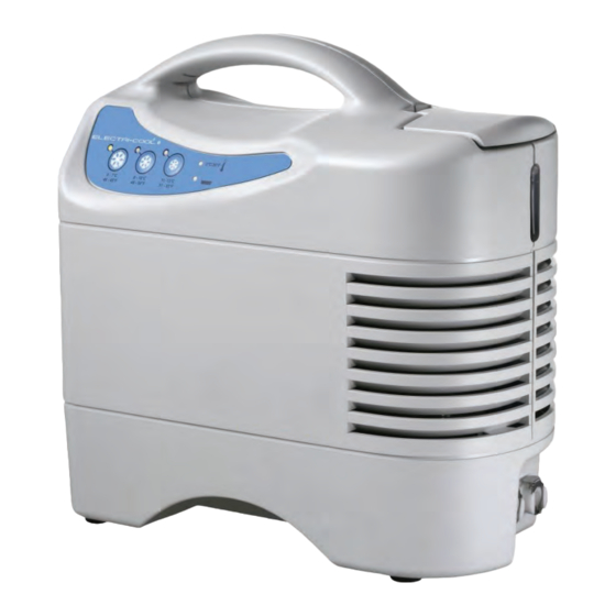
Gentherm Electri-Cool II Operation And Technical Manual (140 pages)
Brand:
Gentherm
| Category:
Medical Equipment
| Size: 5.87 MB
Table of Contents
Table of Contents
3
Introduction
15
Receiving and Inspection/ Important Safety Information
15
General Safety Precautions
15
General Product Description
15
Indications for Use
16
Contraindications
16
Transporting and Shipping
16
General Safety Precautions
16
Warnings
17
Cautions
17
Symbols on the Device and in the Manual
19
Table 1 Device and Manual Symbols
19
Serial Number
21
Warranty
21
Receiving Inspection and Setup
21
Technical Help
21
Authorized European Representative
21
Introduction
22
Before You Call for Service
22
Setup
23
Equipment Set-Up
23
Mounting the Unit to a Bed Bracket
23
Reservoir Filling Instructions
24
Startup Instructions
24
Setting Temperature
24
Accessories
26
Pad Instructions
27
Disposal
27
Cleaning (External)
27
Storage
28
Electromagnetic Emissions
28
Table 2 Presented in Fulfillment of IEC 60601-1-2
28
Table 3 Electromagnetic Immunity
29
Maintenance
32
Overview
32
Inspection Frequency
32
Exterior Physical Inspection & Cleaning
32
Draining the Reservoir
32
Air Filter Inspection and Replacement
33
Remove the Filter Retainer
34
Draining the Reservoir
36
Troubleshooting Guide
38
General
38
Indicator Specifics
39
Service
40
ECII Interior Access
41
Flow Test
42
Water Leak Test
42
Temperature Test
42
Low Water Switch/Indicator Test
43
Leakage Current Test
44
Ground Continuity Test
44
Water Temperature Low-Limit Thermistor Test
44
Internal Physical Inspection
45
Preventive Maintenance for Service Personnel
47
Table 5 Preventive Maintenance Inspection Sheet
47
Table
50
Rear Enclosure and Reservoir Lid Replacement
52
Rear Enclosure and Reservoir Lid Removal
53
Rear Enclosure and Reservoir Lid Installation
55
Front Enclosure Replacement
57
Front Enclosure Removal
58
Front Enclosure Installation
59
Figure 30 Step 5 Reconnect Ribbon Cable
59
Bottom Enclosure Replacement
61
Bottom Enclosure Removal
62
Bottom Enclosure Installation
63
Equipotential Grounding Stud Replacement
64
Grounding Stud Removal
64
Figure 37 Step 2 Remove Ground Wire and Second Keps Nut
64
Grounding Stud Installation
65
Figure 39 Step 2 Add the Green and Gold Ring
65
Figure 41 Step 5 Attach Ground Wire and Second Keps Nut
66
Membrane Panel Replacement
67
Membrane Panel Removal
68
Figure 43 Step 4 Push Flat Screwdriver through Cable Slot from the Inside
68
Membrane Panel Installation
69
Figure 44 Step 1 Thread Cable through Slot
69
Float Switch Replacement
70
Float Switch Removal
71
Figure 47 Step 4 Loosen Reservoir Insulation
71
Figure 48 Step 5 Unscrew Float Switch Mounting Nut
71
Float Switch Installation
72
Figure 50 Step 2 Thread Wires through Gasket
72
Figure 51 Thread Connector and Wires through Reservoir
72
Figure 52 Step 4 Secure Float Switch Mounting Nut
73
Figure 53 Step 5 Loosen Reservoir Insulation
73
Figure 54 Step 6 Route Wiring Behind Bracket
73
Reservoir Replacement
75
Reservoir Removal
76
Reservoir Installation
77
Figure 58 Step 1 Connect Tubing to Reservoir with Clamps
77
Figure 59 Step 3 Float Switch Wires Position
77
Pump Replacement
78
Pump Removal
79
Figure 63 Step 5 Remove EMI Suppressor
79
Figure 64 Step 7 Remove Discharge Tubing
80
Figure 66 Step 6 Unscrew Pump Bracket from Base Enclosure
80
Figure 68 Step 1 Remove Pump from Bracket
81
Pump Installation
82
Figure 71 Step 3 Slide Tubing Onto New Pump
82
Figure 72 Step 4 Tighten the Hose Clamps
83
Figure 74 Step 6 Wire Tie below EMI Suppressor
83
Figure 76 Step 8 Route Wires Behind Bracket
84
Figure 77 Step 9 Connect Power Wire Connector to J5
84
Quick Disconnect Panel Mount Couplings Replacement
85
Quick Disconnect Removal
86
Figure 78 Step 4 Tubing at 90 Degree Elbow
86
Figure 79 Step 5 Remove Tubing from Pump
86
Figure 81 Step 7 Pull Couplings out of Enclosure
87
Quick Disconnect Installation
88
Figure 82 Slide Retainer Nuts Onto Tubing
88
Figure 83 Step 6 Extend Tubing through Enclosure
88
Figure 84 Step 7 Insert Couplings into Hose
89
Figure 88 Step 12 Apply Electrical Tape Around Insulation
90
Fuse Replacement
91
Fuse Removal
92
Fuse Installation
93
Power Inlet and Wire Harness Replacement
94
Power Inlet Removal
95
Figure 95 Step 3 Plastic Power Inlet Shroud
95
Figure 96 Step 4 Remove Retaining Keps Nut and Ground Wires
95
Figure 97 Step 5 Disconnect Harness from the Power Supply
96
Power Inlet Installation
98
Figure 102 Step 3 Connect Control Board Wires to J2
98
Figure 104 Step 5 Route Wire Harness Connector Behind Bracket
99
Figure 106 Step 7 Attach All Grounding Wires
99
Figure 107 Step 8 Reinstall Plastic Power Inlet Shroud
100
Control Board Replacement
101
Control Board Removal
102
Figure 108 Step 3 Disconnect All 5 Connectors
102
Figure 109 Step 4 Remove Three Plastic Screws
102
Figure 110 Step 5 Remove Three Plastic Washers (One Shown)
102
Control Board Installation
103
Figure 111 Step 1 Remove Three Plastic Washers (One Shown)
103
Figure 112 Step 2 Reinstall Three Plastic Screws
103
Power Supply Replacement
104
Power Supply Removal
105
Figure 114 Step 4 Unscrew Power Supply from Front Bracket
105
Figure 115 Step 5 Control Board Power Wire Harness
105
Figure 116 Step 6 Remove Phillips Screws from Rear Braket
106
Figure 117 Step 7 Disconnect Power Supply Wires to Power Inlet
106
Figure 118 Step 8 Remove Wire Tie on Power Supply
106
Power Supply Installation
107
Figure 119 Step 1 Connect Power Supply Wires from Power Inlet
107
Figure 120 Step 2 Install Two Truss-Head Screws on Rear Bracket
107
Figure 121 Step 3 Connect Fan Wires to the Power Supply
107
Figure 123 Step 5 Power Supply Wires Placement
108
Figure 124 Step 6 Secure Power Supply Wires to Front Bracket
108
Figure 125 Step 7 Wire Tie the Harness to the Third Slot
109
Thermoelectric (TE) Module Replacement
110
TE Module Removal
111
Figure 126 Step 5 Remove Screws and Plastic Spacers
111
Figure 127 Step 6 Remove Two Screws Attaching the te Module to the Back Bracket
111
Figure 128 Step 7 Remove Tubing from te Module
112
TE Module Installation
113
Figure 130 Step 2 Install 2 Screws Attaching te Module to the Front Bracket
113
Figure 131 Step 3 Install 2 Screws and Spacers
113
Fan Motor Replacement
115
Fan Motor Removal
116
Fan Motor Installation
117
Figure 134 Step 1 Install Four Screws into Fan Guard Holes
117
Figure 135 Step 2 Place Filter into Retainer
117
Figure 136 Step 3 Re-Attach Filter Retainer
117
Figure 139 Step 6 Place Fan over te Brackets on Fan Guard Screws
118
Fan Guard Replacement
120
Fan Guard Removal
121
Fan Guard Installation
124
Figure 152 Step 6 Place Plastic Shield in Position
125
Specifications
127
Expected Service Life
128
Replacement Parts
132
Advertisement
Advertisement
Related Products
Gentherm 767
Gentherm BLANKETROL CoolRepeat
Gentherm CSZ Blanketrol II 222S
Gentherm STIHLER ELECTRONIC ASTODIA DIA100
Gentherm STIHLER ELECTRONIC ASTODIA DIA120
Gentherm STIHLER ELECTRONIC ASTODIA DIA130
Gentherm Categories
Medical Equipment
Portable Generator
Inverter
Indoor Furnishing
Personal Care Products
More Gentherm Manuals
Login
Sign In
OR
Sign in with Facebook
Sign in with Google
Upload manual
Upload from disk
Upload from URL