Sign In
Upload
Manuals
Brands
Geely Manuals
Engine
JL481Q
Geely JL481Q Manuals
Manuals and User Guides for Geely JL481Q. We have
1
Geely JL481Q manual available for free PDF download: Manual
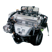
Geely JL481Q Manual (199 pages)
Brand:
Geely
| Category:
Engine
| Size: 14.36 MB
Table of Contents
Table of Contents
2
Chapter 1 Engine Overview
5
Section 1 Basic Structure and Working Principle of Engine
5
Operational Principle of Engine
6
Cooling System
6
Lubricating System
6
Intake Stroke
7
Compression Stroke
7
Power Stroke
7
Exhaust Stroke
7
Section 2 Structural Characteristic of Engine
8
Components Assembly Drawing
9
Engine and Its Power System Diagram
10
Assembly Drawing of Engine and Its Auxiliaries
11
Electronic Control Fuel Injection System Diagram
12
Engine Front View
13
Sectional Elevation
14
Electronic Control Fuel Injection System Engine
15
Section 3 Engine Technical Performance and Parameters
16
Engine Performance Curve
18
Engine Servicing Specifications
22
Section 4 Engine Servicing Datasheet
22
Maintenance Periods and Maintenance Content
27
Maintenance of Lubricating System
27
Section 5 Maintenance of Engine
27
Maintenance of Cooling System
28
Check of Engine
28
Check and Replacement of Timing Belt
28
Check and Measurement of Valve Clearance/Pump Driving (V-Type) Belt
28
Replacement of Oil Filter
29
Check and Replacement of Spark Plug
29
Replacement of Compulsory Ventilation Valve PCV in Crankshaft Box
29
Check and Replacement of All Hoses and Connections in Engine
29
Chapter 2 Cylinder Block Assembly
30
Section 1 Structural Characteristic of Cylinder Block
30
Grouped Servicing Data for Cylinder Block
31
Section 2 Detach, Assembly and Servicing of Cylinder Block
31
Preparations before Detaching and Checking the Cylinder Block
33
Remove the Engine-Power Train (with Clutch and Gearbox)
33
Detach the Cylinder Head Sub-Assy. off the Engine Assy.
33
Disassembly, Examination and Servicing of Cylinder Block
38
Abrasion Characteristics of Engine Cylinder Bore
40
Bore and Grind the Cylinders
43
Reassembly
44
Reinstallation
44
Chapter 3 Cylinder Head Assembly
49
Section 1 Structural Characteristic of Cylinder Head
49
Section 2 Detach, Assembly and Repair of Cylinder Head
49
Cylinder Head Inspection
50
Clean Piston-Top Surface and Cylinder Block
50
Clean Cylinder Head
50
Check Cylinder Head
51
Clean Valve
51
Check Valve Stem and Valve Guide
52
Check Valve Seat
53
Check Valve Spring
55
Check Camshaft and Bearing
55
Check Radial Run out of Camshaft
55
Check Cam Peach-Tip
55
Check Oil Clearance on Camshaft Journal
56
Check Axial Clearance of Camshaft
57
Check Backlash of the Camshaft Gear
57
Check Valve Tappet and Tappet Pore Diameter
57
Check Cylinder Head Bolt
57
Replacement of Valve Guide
58
Replacement of Oil Seal on Spark Plug Guide
59
Installation of Cylinder Head
60
Tighten the Bolts on the Cylinder Head
62
Mount the Intake Camshaft
62
Mount Air Inlet/Exhaust Camshafts
63
Inspect and Adjust the Clearance of Valves
65
Mount Timing Pulley of Camshaft
65
Mount the Timing Pulley
66
Inspect Valve Timing
66
Inspect the Belt Deflection
67
Mount the Semi-Circle Plug
67
Mount Cylinder Headcover
67
Mount Spark Plug
67
Mount Oil Dipstick and Guide Tube
68
Mount Intake Manifold
68
Mount Fuel Injector and Fuel Delivery Pipes
68
Connect the Inlet Fuel Hoses to Delivery Pipes
69
Mount Water Bypass Hoses and Fuel Return Hoses
69
Use Two Bolts to Fix Air Intake Manifold Support Stay
70
Mount Throttle Body
70
Mount Water Inlet Port and Its Shield
70
Mount Ignition Control Device
71
Install Water Outlet Pipe
71
Mount Exhaust Manifold
71
Mount AC Generator
72
Make Connection of Engine Wire Harness
72
Filling Engine Coolant
72
Structural Characteristics of Piston, Piston Pins and Piston Rings
73
Chapter 4 Piston & Connecting Rod Mechanism
73
Section 1 Construction of Piston & Connecting Rod Mechanism
73
Piston Pin
74
Piston Ring
74
Structural Characteristics of the Connecting Rod and Its Bearing Shell
75
Section 2 Dismantling and Inspection of the Connecting-Rod and Its Bearing
76
Technical Data for Common Repair of Connecting-Rod and Its Bearing
77
Section 3 Common Faults and Troubleshooting of the Piston Connecting-Rod Mechanism
77
Damage of the Piston Pin
78
Broken or Ablated Piston Ring
78
Maintenance Data for the Piston Ring
78
Damage of the Connecting-Rod
79
Crankshaft
80
Chapter 5 Crank Mechanism
80
Section 1 Structural Characteristics of Crank Mechanism
80
Main Bearing
81
Crankshaft Thrust Washer
82
Flywheel
82
Detaching of Flywheel
82
Section 2 Disassembly & Maintenance of Crank Mechanism
82
Installing Crankshaft
85
Grouping of Crankshaft Joumal & Bearing Shell Dimensions
85
Commonly-Used Servicing Data
86
Install Flywheel Subassembly
86
Servicing Data of Main Bearing Journal and Bearing Shell
86
Grouping Data of Connecting-Rod Journal and Bearing
86
Cracking & Fracture of Crankshaft
87
Wear of Flywheel Working Face and Damages to Gear Ring
87
Section 3 Common Faults and Troubleshooting of Crank Mechanism
87
Section 2 Disassembly & Maintenance of Crank Mechanism
87
Chapter 6 Valve Train
88
Section 1 Make-Up of Valve Train & Its Design Features
88
Characteristics of Valve Train
89
Section 2 Valve Timing
89
Crankshaft Timing Pulley
90
Camshaft Timing Pulley
90
Section 3 Make-Up of Valve Train Assembly and Its Features
90
Timing Belt
91
Camshaft
91
Valve
91
Valve Seat Insert
92
Valve Tappet
92
Valve Spring
92
Camshaft and Bearing Seat
93
Valve Train Assy.
93
Service of Timing Gear, Belt and Tensioner
93
Section 4 Service of Valve Train
93
Positioning and Installation of Valve Train
94
Tensioner
94
Timing Gear
94
Common Servicing Data
95
Servicing Data of Valve Train
95
Valve Leakage
97
Valve Sticking or Scorching
97
Valve Seat Damage/Invalid Valve Spring
97
Section 5 Common Faults and Troubleshooting of Valve Train
97
Chapter 7 Fuel Supply System
98
Section 1 Makeup and Features of Fuel Supply System for Electronic Fuel Injection Engine
98
Fuel Filter
101
Fuel-Pressure Regulator
101
Fuel Injector
102
Gasoline Vapor Recovery Installation
102
Section 2 Matters Needing Attention in Use and Maintenance of Electronic Fuel Injection System
103
Air Intake System
104
Electronical Controlled System
104
Fuel System
105
Examination of Fuel Pressure Regulator
106
Examining Fuel Pressure on the Car
106
Section 3 Troubleshooting the Electronic Fuel Injection System
106
Detaching the Fuel Pressure Regulator
107
Install the Fuel Pressure Regulator
107
Measure the Fuel Pressure
107
Injector Examination
109
Injector Detaching
109
Detaching and Disassembling Injector and Fuel Delivery Pipe
110
Injector Installation
113
Examine Injector Leakage
113
Examination of Throttle Body
114
Detaching Throttle Body
114
Installation of Throttle Body
116
Examination of Idling Speed Control (ISC) Valve
117
Examination of EFI Main Relay
118
Examination of Vacuum Solenoid Valve (VSV)
119
Examination of Intake Pressure & Temperature Sensor
121
Examination of Water Temperature Sensor
122
Examination of Knock Sensor (KNK)
123
Examination of Electronically Controlled Unit (ECU)
123
Examine the ECU Voltage
123
Examination of Fuel-Cut Speed
124
Pin Voltage Definition
124
Examination of Oxygen Sensor
125
Matters Needing Attention Items Related to Use Catalytic Converter
126
Examination of Fuel Pump System Circuit
126
Section 4 Evaporative Emission & Positive Crankcase Ventilation Control System
128
Examination of Positive Crankcase Ventilation System
129
Examination of Evaporative Emission Control System
129
Ignition Control
131
Chapter 8 Ignition System
131
Section 1 Introduction to Ignition System
131
Examination of Ignition System on the Car
132
Examination of High-Tension Spark
132
Section 2 Troubleshooting of Ignition System
132
Examination of High Voltage Wires
133
Examination of Spark Plugs
134
Oil Passage Within Lubrication System
136
Chapter 9 Lubrication System
136
Section 1 Makeup and Features of Lubrication System
136
Structure and Features of Engine Oil Pump
137
Structural Features of Engine Oil Filter
138
Positive Crankcase Ventilation (PCV)
139
Examination and Maintenance of Engine Oil Pump
140
Section 2 Examination & Maintenance of Lubrication System
140
Reassembly of the Oil Pump
142
Engine Oil Examination & Engine Oil Filter Troubleshooting
143
Lubrication System Maintenance Data
144
Over-Low Engine Oil Pressure
145
Over-High Engine Oil Pressure
145
Engine Oil Deterioration
145
Section 3 Common Faults and Troubleshooting of Lubrication System
145
Excessive Engine Oil Consumption
146
Chapter 10 Cooling System
147
Section 1 Composition & Features of Cooling System
147
Structure & Features of Water Pump
148
Structure & Features of Thermostat
148
Specification of Thermostat
149
Temp.control Electric Fan
150
Radiator Temperature Detect Switch
151
Cleaning and Maintenance of Radiator
151
Inspection on Radiator Cover
151
Section 2 Inspection and Maintenance of Cooling System
151
Inspection & Maintenance of Water Pump
152
Inspection on Thermostat
152
Water Filling and Air Exhaust
153
Abrupt Overheat
153
Section 3 Common Faults and Troubleshooting of Cooling System
153
Chapter 11 Clutch
154
Section 1 Structure of Clutch and Its Operating Mechanism
154
Release Mechanism
155
Structure of Clutch Operating Mechanism
156
Clutch Detaching
156
Section 2 Clutch Troubleshooting
156
Detach of Clutch Operating Mechanism
157
Clutch Inspection and Maintenance
157
Inspection and Maintenance of Clutch Operating Mechanism
158
Section 3 Assembly and Adjustment of Clutch and Its Operating Mechanism
159
Clutch Operating Mechanism Assembly
160
Clutch Adjustment
161
Clutch Maintenance
162
Clutch Slippage
162
Section 4 Common Faults and Troubleshooting of Clutch
162
Clutch Can’t Seperate or Incomplete Release
163
Clutch Noise
163
Clutch Shuddering
163
Starter Does Not Rotate, or Cannot Drive the Engine to Rotate
164
Engine Cannot Start and There Is no Ignition Signs
164
Chapter 12 Common Faults and Troubleshooting of Engine
164
Section 1 Overview
164
Section 2 Determination and Elimination of Common Faults in Engine
164
With Ignition Signs, It Still Fails to Start
165
Oil and Circuit Faults that Cause the Engine Hard to Start
166
Engine Cannot Start
167
Engine Is Hard to Start
168
Oil and Circuit Faults that Reduce Engine Performance
169
Insufficient Power
169
Poor Deceleration
169
Poor Acceleration
169
Large Fuel Consumption
171
Idle Speed Is Not Stable, Tends to Flameout
172
Idle Speed of Cold Auto Is Not Stable, Tends to Flameout
173
Idle Speed of Warm Auto Is Not Stable, or Flameout Occurs
173
Idle Speed Is too High for Warm Auto
173
Idle Speed Fluctuation
173
Exhaust Smoke from Exhaust Pipe Is Abnormal
174
Engine Overheats
174
Exhaust Smoke Is very Dark
174
Exhaust Smoke Is Blue with Unusual Odor
174
Abnormal Noise of the Camshaft
175
Slap Noise in Valve Set
175
Cause of Abnormal Noise in Crankshaft Linkage and Elimination Method
175
Section 3 Determination and Elimination of Abnormal Noises in the Engine
175
Cause of Abnormal Slap Noise in Piston Ring and Elimination Method
176
Cause of Abnormal Piston Knock Noise and Elimination Method
176
Alternator and Regulator
177
Chapter 13 Power Source
177
Section 1 Structure of Clutch and Its Operating Mechanism
177
Alternator Check
178
Alternator Application and Maintenance
178
Structure of Lead Battery
179
Normal Malfunction Elimination of Battery
179
Section 2 Battery
179
No Charging Completely
180
Low Charging Current
180
Section 3 Normal Malfunction of Charging System and Troubleshooting
180
Chapter 14 Starter
181
Section 1 Structure of Starter
181
Section 2 Working Principle of Starter
182
Section 3 Attentions in Use of Starter
182
Starter Not Rotate
183
Powerless Running of Starters
183
Difference of Magnetic Switch Failure and Starter Failure
183
Section 4 Troubleshooting of Starter
183
Electronic Control of Engine Fuel System
184
Electronic Control of Engine Ignition System
184
Chapter 15 Engine Management System
184
Section 1 System Profile
184
Hardware Composition of Electronic Control Unit
185
Section 2 System Composition and Working Principle
185
Input Stage
186
Microcomputer
186
Output Stage
186
Schematic Diagram of the Fuel Injector
188
Chapter 16 Engine Electronic Control System
188
Section 1 General Structure of Engine Electronic Control System
188
Section 2 Structural Principle of the Components of the Engine Electronic Control System
188
Idle Control Solenoid Valve
189
Technical Parameters of EWD3 Idle Speed Regulator
189
Stepper Motor
189
Technical Parameters of EV6 Fuel Injector
189
Performance Data
190
Intake Pressure & Temperature Sensor
191
Water Temperature Sensor
192
Technical Parameters of DS-S/TF Pressure Sensor
192
Speed Sensor
193
Ignition Coil
193
Pressure Regulator
194
Phase Sensor
194
Throttle Position Sensor
195
Knock Sensor
196
Carbon Canister Control Valve
196
Oxygen Sensor
197
Electric Fuel Pump
198
Advertisement
Advertisement
Related Products
Geely JL50QT-21
Geely MR479Q
Geely MR479QA
Geely MR481QA
Geely Categories
Automobile
Scooter
Engine
Car Video System
More Geely Manuals
Login
Sign In
OR
Sign in with Facebook
Sign in with Google
Upload manual
Upload from disk
Upload from URL