Sign In
Upload
Manuals
Brands
GEA Manuals
Commercial Food Equipment
MultiFormer 600
GEA MultiFormer 600 Manuals
Manuals and User Guides for GEA MultiFormer 600. We have
1
GEA MultiFormer 600 manual available for free PDF download: Original Operating Instructions
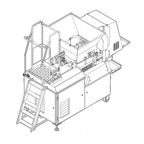
GEA MultiFormer 600 Original Operating Instructions (94 pages)
Forming machine
Brand:
GEA
| Category:
Commercial Food Equipment
| Size: 5 MB
Table of Contents
EC - Declaration of Conformity for Machines
3
Table of Contents
5
Safety
11
Important Information
11
Warning Signs
12
Classification of Safety Signs
12
Signs on the Machine
13
Danger, Warning, Caution and Attention
13
Intended Use
14
Modifications
14
Safety Devices
15
Emergency Stop
15
Cover Guards
15
Signs on the Machine
15
Password
15
Safety Precautions
16
During Normal Production
16
During Maintenance and Repair
16
Hygiene Levels
17
Areas at the Machine
17
Definitions
17
Special Hygiene Rules
17
Users
18
Personnel Qualifications
18
Personal and Food Hygiene
18
Disposal
19
For Economic Purpose
19
Final Disposal
19
Further Help and Information
19
Description
21
Main Items
21
Working Principle
22
Hopper
22
Press Block
22
Forming Unit
22
Tooling Set & Filling Set
23
Knockout Unit
23
Conveyor
23
Form Plate Support
23
Specifications
24
Standard Machine
24
Form Plate Dimensions
24
Ambient Conditions
24
Type Plate
24
Control Panel
25
Main Menu
25
Menu Structure
25
Screen
25
Screen Header
26
Menu Bar
26
Central Workspace
27
Main (Screen 1)
27
Production
28
Menu Structure
28
Screen 1000
29
Screen 1001
29
Screen 1002
29
Screen 1022
30
Screen 1003
30
Screen 1004
30
Screen 1005
30
Screen 1006
31
Screen 1007
31
Screen 1008
31
Screen 1009
31
Screen 1010
32
Screen 1011
32
Cleaning
33
Menu Structure
33
Maintenance
34
Menu Structure
34
Statistics
36
Menu Structure
36
System Settings
37
Menu Structure
37
Offline Recipe
39
Menu Structure
39
Alarms
40
Menu Structure
40
Transport and Installation
41
Transport
41
General
41
Internal Transport
41
Installation
42
General
42
Platform
42
Electricity
42
Connections
42
Password GEA Control
42
Conveyor Belt Installation
43
Conveyor Belt
43
Conveyor Belt Position
43
Operation
45
Overview
45
Control Buttons
45
Settings before Production
45
Handling of the Plates
46
Storage of the Plates
46
Daily Inspection
46
Exchange the Form Plate
47
Raise the Hopper
47
Install the Support Block
47
Install the Bottom Plate
47
Install the Form Plate
48
Install the Top Plate
48
Remove the Support Block
48
Lower the Hopper
48
Exchange the Plates for 3D and Double-3D Products
49
Install the Double-3D Plate
49
Install the 3D Form Plate
49
Install the Top 3D Plate
50
Exchange the Knockout
51
Attach the Knockout Unit
51
Disassemble the Knockout Unit
51
Check the Alignment
51
Production
52
Start
52
Slow Start
52
Normal Start
52
Recipe Handling
53
Load a Recipe
53
Save a Recipe
53
Adjustments During Production
53
Empty the Hopper
54
Stop Production
54
Cleaning
55
General
55
Machine
55
Personnel
55
Chemicals
55
Instructions
55
Day-To-Day Cleaning
56
Cleaning Detergents
57
Detergents
57
Equipment
59
Cleaning Equipment
59
Cleaning Water
59
Water Hardness
59
Water Quality
59
Cleaning Procedure
60
Moving the Machine
60
Hopper
60
Press Block Cleaning
61
Press Block
61
Air Venting Pipe Assembly
61
Knockout
61
Tooling Set
61
Conveyor
62
Collection Tank
62
Control Panel
62
Product Contact Surface
62
Cleaning Stainless Steel
63
Introduction
63
Cleaning
63
Slight Pollution
63
Strong Pollution & Slight Damage
63
Water Consumption
63
Maintenance
65
Safety
65
Activity Matrix
66
Daily
66
40 Hours
66
2000 Hours
67
Lubrication
68
Machine Parts
68
Wire Mesh Belt
68
Wire Condition
68
Wire Connection
68
Wire Tension
68
Knockout Alignment
69
Sideways Knockout Position
69
Form Plate Position
69
Knockout Cylinder Rod End Bearing
70
Rod End Bearing
70
Assembly
70
Knockout Mechanism
71
Bearing
71
Assembly
71
Knockout Cylinder
72
Cylinder
72
Assembly
72
Form Plate Cylinder
73
Form Plate Connection Bracket
73
Cylinder
73
Assembly
73
Press Block Seal
74
Press Block
74
Guiding Block
74
Guiding Sleeve
74
Inspection
75
Assembly
75
Press Block Guiding Blocks
75
Augers
76
Rubber Bushes
76
Assembly
76
Auger Drive Unit
77
Covers & Hydraulic Motors
77
Gears
77
Inspection
77
Assembly
77
Auger Bearings
78
Hydraulics Calibration
78
Form Plate Cylinder Pressure
78
Press Block Cylinder Pressure
78
Pressure Switch
79
Adjustment of the Pressure Switches
80
Hopper Lift Mechanism
81
Support Blocks
81
Cross Beam
81
Assembly
81
Troubleshooting
83
Safety
83
Emergency Stop
83
Error Messages
84
Operator
84
Service Personnel
85
Observed Deviations
86
Machine Problems
86
7.3.1.1 Operator
86
7.3.1.2 Service Personnel
86
Product Problems
87
Product Problem Descriptions
88
Air Pressure
88
Adjustment
88
Manual Operation
89
Pneumatic Valves
89
Hydraulic Valves
89
Linear Position Sensor Calibration
89
Hydraulic Pump Coupling
90
Form Plate Connection Bracket
91
Removal
91
Assembly
91
Press Block Stroke Adjustment
91
End-Buffer Cylinder Adjustment
91
Detention Rubber Adjustment (400 Only)
92
Place the Filling Strip (Option: Type 600)
93
Disassembly
93
Assembly
93
Place the Filling Strip
93
Product Temperature Control
93
Advertisement
Advertisement
Related Products
GEA Hilge NOVALOBE 60
GEA E022110205312
GEA Categories
Control Unit
Air Compressor
Water Pump
Compressor
Industrial Equipment
More GEA Manuals
Login
Sign In
OR
Sign in with Facebook
Sign in with Google
Upload manual
Upload from disk
Upload from URL