
Summary of Contents for GEA MultiFormer 600
- Page 1 GEA MultiFormer 600 Machine number: E022110205312 Customer: Sol Cuisine Original operating instructions Date: 03-2019...
- Page 2 No part of this publication may be reproduced, transmitted, transcribed, stored in any retrieval system or translated into any human or computer language by any means or in any form, without the prior written permission of GEA Food Solutions Bakel B.V.
-
Page 3: Ec - Declaration Of Conformity For Machines
EC - Declaration of conformity for machines in accordance with EC Machinery Directive 2006/42 /EC, Annex II 1. A Manufacturer: GEA Food Solutions Bakel B.V. Beekakker 11 5761 EN Bakel, The Netherlands We, as manufacturer, declare in sole responsibility that the machinery... - Page 4 About this manual The GEA MultiFormer, hereafter referred to as ‘the machine’, is manufactured by GEA. This manual provides information about day-to-day use, cleaning, mainte- nance and repair. Subject(s) Chapter(s) Intended user(s) Safety, Description 1, 2 All authorised personnel Transport, installation...
-
Page 5: Table Of Contents
TABLE OF CONTENTS EC - Declaration of conformity for machines ......3 SAFETY ............11 Important information . - Page 6 Password GEA control ........
- Page 7 OPERATION ........... . 45 Overview .
- Page 8 Water quality ..............
- Page 9 6.2.7 Form plate cylinder ............. .
- Page 10 Hydraulic valves .............
-
Page 11: Safety
- usually a company or a corporation. An operator is a person who phys- ically interacts with the machine and/or the machine's control systems under the direction and with the consent of the machine's user. In GEA manuals, an operator includes a person who cleans the machine. -
Page 12: Warning Signs
Warning! Do not use the machine until you have received adequate and proper train- ing in its safe and effective use. If you are unsure of your ability to use the machine safely and effectively, do not do so. For information about training, refer to ‘Further help and information’... -
Page 13: Signs On The Machine
Signs on the machine Signs Keep hands away from au- High voltage. gers. Hearing protection compul- Safety shoes compulsory. sory. Slippery surface. Read the manual. Hand injury. Lift position. Danger, Warn- Warning notices are classified according to the level of danger that hazardous sit- ing, Caution and uations present. -
Page 14: Intended Use
Any other or additional use will be considered to be not in conformity with the pur- pose. GEA will not accept any liability for improper use. Use this machine in a technical perfect condition in conformity with the purpose described above. -
Page 15: Safety Devices
– Replace or repair signs that have become illegible or damaged. Password To get access to a level of the system, personnel must enter a password. Chang- ing a password is reserved to local service engineers and to the GEA service en- gineer (level 5). 0000010291... -
Page 16: Safety Precautions
Safety precautions During normal The machine must only be operated when the cover(s) is (are) closed. production – Be sure that there is nobody in its immediate vicinity; – Make sure that the environment around the machine is dry, clean and lit suffi- ciently well;... -
Page 17: Hygiene Levels
Hygiene levels Areas at the ma- chine Non-product Splash area. Product contact contact surface. (Yellow) surface. (Red) (Green) Definitions Product contact surface Machinery surfaces that are exposed to the product and from which the other ma- terials can drain, drip, diffuse or be drawn into (self-returned) the product or prod- uct container. -
Page 18: Users
Users Personnel quali- – The machine is designed only for personnel being 14 years or older. Consider fications the respective national regulations for occupational safety and health; – Only personnel who have been given permission are allowed to work with or on the machine;... -
Page 19: Disposal
Disposal For economic GEA offers you a return policy for used GEA machines. Contact your local sales purpose representative for details. Final disposal The use and maintenance of the machine includes no environmental dangers. Most parts can be disposed in the regular way. - Page 20 0000010291...
-
Page 21: Description
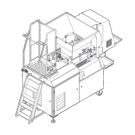
DESCRIPTION Main items Hopper B Press block C Knockout unit D Form plate E Conveyor Drip tray G Control panel H Steps Platform 0000010291... -
Page 22: Working Principle
Working principle Within the machine there are five main functions. These five functions represent the working of the machine. Hopper – contains the product to be processed; – feeds the product into the press block. Press block – pressurizes the product; –... -
Page 23: Tooling Set & Filling Set
Tooling set & filling set – consist of product specific parts (tooling set) and product independent parts (filling set). Knockout unit – knocks the formed product out of the form- ing unit. Conveyor – transports the formed product from the ma- chine. -
Page 24: Specifications
5 °C < T < 40 °C Relative humidity < 95 % Type plate The (standard) GEA type plate is located on the back of the machine. The type plate contains information about the items, listed below: Item Type Machine serial number... -
Page 25: Control Panel
Control panel 2.4.1 Main menu Menu structure 1000 2000 3000 4000 5000 7000 8000 Screen Title Level Main Operator 2.4.3 1000 Production Operator 2.4.4 2000 Cleaning Operator 2.4.5 3000 Maintenance Service 2.4.6 4000 Statistics Service 2.4.7 5000 System settings Service 2.4.8 7000 Offline recipe... -
Page 26: Screen Header
Screen header Shortcut icon B Screen title C Screen number. Shortcut to the screens with a keypad. D User level E Password Recipe number G Title on-line recipe H Status line Date Time K Alarm icon Header icons Go to screen 8000. Alarm in- dicator: Shortcut to the main screen. -
Page 27: Central Workspace
Select a recipe or acknowl- Scroll screen down. edge an alarm. Central work- The central workspace is unique for every screen. The workspace can contain space these items: – Icons: Activate a machine function/action or show the condition of a machine part. -
Page 28: Production
2.4.4 Production Menu structure 1000 1001 1100 1300 1011 1301 1302 1305 1306 1304 Screen Title Level Description 1000- Production Operator To set the production settings. Ex- 1011 plained in this section. 1100 Load recipe Operator To select a recipe. 1300 - Manual Operator To start a part of the machine manu-... -
Page 29: Screen 1000
Production speed. Press block pressure. Overlapping stacks. Auger time. High-capacity paper inter- Augers on/off menu. Go to leaver. screen 1301. Conveyor on/off menu. Go to Knockout up/down menu. Go screen 1302. to screen 1304. Form plate in/out menu. Go Press block up/down menu. to screen 1305. -
Page 30: Screen 1022
Screen 1022 Item Description Form plate > stroke: The stroke length of the form plate needs to be filled. length [mm] Form plate > position The position of the form plate (outwards stroke) (press blocks: up) [mm] where the press block is raised. Form plate >... -
Page 31: Screen 1006
Screen 1006 Item Description Nozzle (knockout) > de- The delay time before the nozzle starts to spray after lay time [s] the form plate is in the knockout position. (0 - 3 sec- onds) Nozzle (knockout) [s] The time the nozzle sprays water. (0 - 1 seconds) Bridge breaker To activate the bridge breaker in the hopper. -
Page 32: Screen 1010
Screen 1010 Item Description Form plate > stop mo- The time the form plate stops in the outfeed stroke for ment [s] the stick inserter to insert the sticks. (0 - 1 seconds) Form plate > halt time The duration the stick inserter presses the sticks into the product. -
Page 33: Cleaning
2.4.5 Cleaning Menu structure 2000 2001 2002 Screen Title Level Description 2000 Cleaning Opera- Cleaning selection menu. 2001 Cleaning timer Opera- The cleaning timer counts back from 30 to 0 seconds. During the count back time the touch-screen can be cleaned. -
Page 34: Maintenance
2.4.6 Maintenance Menu structure 3000 3001 3100 3200 3300 3400 3500 3201 3220 3401 3501 3202 3402 3254 3310 3320 3340 3350 3360 Screen Title Level Description 3000 Maintenance 1 Service Maintenance selection menu. 3001 Maintenance 2 Service Maintenance selection menu. 3100 Software Service Gives software version information. - Page 35 Manual menu. Go to screen Start function. 3300. Service settings menu. Go to Data backup menu. Go to screen 3400. screen 3500. Slave 5 menu. Go to screen Augers on/off menu. Go to 3220. screen 1301. Conveyor on/off menu. Go to Knockout up/down menu.
-
Page 36: Statistics
2.4.7 Statistics Menu structure 4000 4100 4200 4103 4210 4220 4230 4240 Scree Title Level Description 4000 Statistics Service Statistics selection menu. 4100- Operating hours Service Gives the operating hours, the 4103 number of starts and the num- ber of overload trips for the ma- chine parts. -
Page 37: System Settings
2.4.8 System settings Menu structure 5000 5001 5002 5100 5200 5300 5110 5301 5302 Screen Title Level Description 5000 System settings 1 Service To change the language, the date and the time. 5001 System settings 2 Service To change the home shortcut. 5002 System settings 3 Service... - Page 38 Touch calibration. 0000010291...
-
Page 39: Offline Recipe
2.4.9 Offline recipe Menu structure 7000 7001 7100 7200 7011 Screen Title Level Description 7000 - Offline recipe Service Offline recipe settings. To set the 7011 same parameters as in the produc- tion menu. Refer to section 2.4.2 "Screen". 7100 Load offline recipe Service To select a offline recipe. -
Page 40: Alarms
2.4.10 Alarms Menu structure 8000 8001 Scree Title Level Description 8000 Actual alarms Operator/ser- Actual alarms and selection screen. vice 8001 Alarm history Operator/ser- Alarm history. vice Icons Actual alarms. Go to screen Extra alarm information. 8000. Alarm history. Go to screen 8001. -
Page 41: Transport And Installation
Improper transport does not entitle the recipient to replacement under the term of warranty. In case of doubt, contact the supplier before transportation. GEA does not accept any responsibility for corrosion damage that occurs due to improper storage, such as in a humid location. -
Page 42: Installation
2. Connect the water supply (A). Use a hose clamp. 3. If desired, connect a water outlet hose to the collection tank. Use a hose clamp. Password GEA The GEA control includes different levels to prevent unauthorized access. control Level Description Default... -
Page 43: Conveyor Belt Installation
Description Default Production Production > development 1604 Maintenance 1310 GEA recommends to change the passwords after installation and from then on ev- ery month. 1. Go to screen 5100 (Password levels). 2. Change the passwords. 3.2.1 Conveyor belt Conveyor belt installation 1. - Page 44 0000010291...
-
Page 45: Operation
OPERATION Warning! Do not attempt to use the machine unless you have read and understood all the information in the safety chapter and you are sure of your ability to use the machine safely; Do not attempt to use the machine unless you know how to stop it in an ... -
Page 46: Handling Of The Plates
4.3.1 Handling of the plates Storage of the The plates have to be properly stored when not installed in the machine. plates Daily inspection 1. Inspect the form plate for cracks. Caution! Dispose of a cracked form plate. Never install a cracked form plate in the machine. -
Page 47: Exchange The Form Plate
4.3.2 Exchange the form plate Caution! Check all plates before use in the machine. Refer to the section 4.3.1 "Handling of the plates". Raise the hop- Warning! Always place a support block when the hopper is raised. This is necessary to prevent crushed fingers due to unintended or accidental lowering. -
Page 48: Install The Form Plate
Install the form plate 1. Lubricate the form plate and the side guides. Use only edible lubricants. Refer to section 6.2.1 "Lubrication". 2. Place the side guides (B) over the threaded rods. The grooves in the side guides must be on the outside. 3. -
Page 49: Exchange The Plates For 3D And Double-3D Products
4.3.3 Exchange the plates for 3D and double-3D products When making 3D or double-3D products the tooling set is different than when making flat products. There is an extra double-3D plate when making double-3D products and there is a different top plate when making double-3D and 3D prod- ucts. -
Page 50: Install The Top 3D Plate
Install the top 3D plate 1. Place the 3D top plate. Warning! The edge of the hole in the top plate is ra- zor sharp. 0000010291... -
Page 51: Exchange The Knockout
4.3.4 Exchange the knockout Attach the knockout unit Attention! Make sure the knockout unit is of the same tooling set as the form plate. 1. Open the front cover. 2. Slide the brackets (B) of the knockout unit over the cams (A). 3. -
Page 52: Production
Production At the start of production it is assumed that: – The hopper is filled with raw material; – The form plate and knockout are installed. Caution! Do not start the machine when the form plate is not lubricated with edible oil. 4.4.1 Start Slow start... -
Page 53: Recipe Handling
4.4.2 Recipe handling Load a recipe 1. Go to screen 1100 (Load recipe). 2. Enter a password, if required. 3. Select the recipe to be loaded. 4. Touch the Confirm icon. Save a recipe 1. Go to screen 1000 (Production 1). 2. -
Page 54: Empty The Hopper
4.4.4 Empty the hopper 1. Push the Hydraulics button. 2. Go to screen 1301 (Augers). 3. Touch and hold the Start icon until the last material is moved to the press block. 4. Push the Production button. 5. Run the machine until the hopper is empty. 4.4.5 Stop production 1. -
Page 55: Cleaning
CLEANING Warning! Do not attempt to clean the machine unless you have read and under- stood all the first aid procedures that apply to your workspace and to the cleaning products that will be used; If there is any safety instruction or procedure that you do not understand, ... -
Page 56: Day-To-Day Cleaning
Day-to-day cleaning Day-to-day cleaning is a task of the cleaning staff (a part of the operators task). The cleaning staff must clean the machine regularly and keep the machine clean. Machine part Method Frequency See Hopper Pressure cleaner Daily 5.3.1 Press block Pressure cleaner Daily... -
Page 57: Cleaning Detergents
5.2.1 Cleaning detergents Warning! Refer to the Material safety data sheet of the chemicals used. Take ap- propriate protection measures; The use of other not verified chemicals could lead to undesirable dam- age of the material surface and so to not cleanable situations. Detergents Cleaning procedure &... - Page 58 Attention! Concentration depends on: the water hardness. Verify the local value. pollution of the machine. Refer to the instructions provided by the man- ufacturer. 0000010291...
-
Page 59: Equipment
Follow the instructions of the foam supplier for proper foaming. 5.2.3 Cleaning water Water hardness The table gains an insight of the values in relation to the water type. GEA recom- mends 5 - 10 °e. Water type Salt concentra-... -
Page 60: Cleaning Procedure
Cleaning procedure Caution! Make sure the shutters for the cooler of the hydraulic unit are closed or cov- ered when using a pressure cleaner. Caution! Close the control panel cover when using a pressure cleaner. Moving the ma- It can sometimes be useful to move the machine to another location for cleaning. chine To move the machine: 1. -
Page 61: Press Block Cleaning
5.3.2 Press block Press block 1. Clean the pressure chamber. Use a pressure cleaner. cleaning 2. Disassemble the press block. Refer to section 7.3.11 "Place the filling strip (op- tion: type 600)". 3. Disassemble the air venting pipes. 4. Clean the pressure chamber and the press block bar. Use a pressure cleaner. 5. -
Page 62: Conveyor
5.3.5 Conveyor 1. Clean the belt. 2. Go to screen 2002 (Conveyor belt). 3. Touch and hold the Start icon until another part of the belt can be reached. 5.3.6 Collection tank 1. Take away the grate. 2. Clean the grate. 3. -
Page 63: Cleaning Stainless Steel
Cleaning stainless steel Introduction Main parts of this machine are designed with stainless steel. This material is ap- plied because of its durability. This durability is secured by – periodic cleaning, – with suitable means and materials, – and with a proper after treatment. Cleaning products have each their own specific effect on stainless steel. - Page 64 Still, there can exist the necessity to have cleaning activities with abundant water. In such cases: protect the machine. 1. Cover the electrical cabinet with plastic material. 2. Check after each cleaning activity if moisture or fluid has entered the electrical cabinet.
-
Page 65: Maintenance
MAINTENANCE Warning! Do not attempt to use the machine unless you have read and understood all the information in the safety chapter and you are sure of your ability to use the machine safely; Do not attempt to use the machine unless you know how to stop it in an ... -
Page 66: Activity Matrix
Activity matrix The activity matrix gives an overview of the maintenance tasks. Daily Inspection Check Action Plates Scratches, burrs and Repair or replace 4.3.1 cracks Cleanliness equip- Contamination Clean, if necessary ment Hydraulic oil level Level Add oil, if necessary - Search for leaks Conveyor belt Damage... -
Page 67: 2000 Hours
Inspection Check Action Augers Damage Repair or replace 6.2.10 Drive unit Repair or replace 6.2.11 Knockout mecha- Wear Replace 6.2.4 / nism 6.2.5 2000 hours Inspection Check Action Hydraulic oil analysis Contamination Replace Oil purity classifica- tion: NAS 1638: 9 ISO 4406: 18 / 15 Conveyor rolls Wear... -
Page 68: Lubrication
6.2.1 Lubrication Machine parts Lubricator Application Frequency Shell Ondina Oil 15 Form plate assembly Daily, first production run Klüber 4UH1-15 Conveyor belt chain and Every 40 hours sprocket Klüber 4UH1-68 Variator Every 2000 hours Klüber paralique GA 351 Bearings Every 2000 hours Shell Tellus T68 Hydraulic oil Every 2000 hours... -
Page 69: Knockout Alignment
6.2.3 Knockout alignment Knockout align- ment Attention! The knockout position is correct when the knockout cups do not touch the form plate but fall into the holes in the plate. The clearance must be the same all round. 1. Push the Hydraulics button. The hydraulic unit starts. -
Page 70: Knockout Cylinder Rod End Bearing
1. Unscrew locknut A. 2. Rotate the cylinder rod to adjust the form plate position. Use a spanner. Warning! Do not damage the piston rod. 3. Adjust until the distance X between the cen- terline of the hole in the form plate and the edge of the base block is 80 mm. -
Page 71: Knockout Mechanism
6.2.5 Knockout mechanism Knockout mechanism 1. Remove the rod head. Refer to section 6.2.4 "Knockout cylinder rod end bearing". 2. Loosen the two bolts (A) on both sides of the machine. 3. Take away the knockout mechanism (B). Bearing 1. Loosen the nylock nuts (A). 2. -
Page 72: Knockout Cylinder
6.2.6 Knockout cylinder Cylinder 1. Disconnect the rod head. Refer to section 6.2.4 "Knockout cylinder rod end bearing". 2. Disconnect the pneumatic hoses and sen- sor wires from the cylinder. 3. Remove the nylock nut (A). 4. Remove the bolt (B). 5. -
Page 73: Form Plate Cylinder
6.2.7 Form plate cylinder Form plate con- nection bracket 1. Remove the lock bolt (D). 2. Take away the pin (B). 3. Slide away the form plate connection brack- et (C). 4. Unscrew the locknut (A). 5. Take away the rod end. Cylinder Warning! Only remove the upper part of the clamping blocks. -
Page 74: Press Block Seal
6.2.8 Press block seal Warning! Do not change the alignment of the guiding of the guiding blocks. Press block 1. Take away the press block. Refer tot section 5.3.2 "Press block". Guiding block 1. Remove the nylock nut (B). 2. Take away the connection pin (D). 3. -
Page 75: Inspection
Inspection 1. Inspect the parts for damage or wear. Replace if necessary. Assembly 1. Assemble the press block seal in the reverse order. Attention! Use Loctite 243 to secure the blocking ring screws. 6.2.9 Press block guiding blocks 1. Take away the press block guiding blocks (A). -
Page 76: Augers
6.2.10 Augers Augers Attention! Depending on the rotation direction of the auger, the bolt can have right or left-handed thread. 1. Take away the air venting pipes. Refer to section 5.3.2 "Press block". 2. Loosen bolt B. 3. Take away the auger (A). From inside the hopper, pull back the auger and lift it out. -
Page 77: Auger Drive Unit
6.2.11 Auger drive unit Covers & hy- draulic motors 1. Take away the augers. Refer to section 6.2.10 "Augers". 2. Loosen the six bolts (F) of the top cover (A) of the auger drive. 3. Take away the top cover of the auger drive. 4. -
Page 78: Auger Bearings
6.2.12 Auger bearings 1. Remove the auger. Refer to section 6.2.10 "Augers". 2. Remove the bearing (A). Use a bearing pull- 3. Press in the new bearing. 4. Install the augers. 6.2.13 Hydraulics calibration Form plate cyl- inder pressure 1. Loosen the sealing plug of MP1 (B). 2. -
Page 79: Pressure Switch
1. Loosen the sealing plug of MP2 (D). 2. Connect a pressure gauge to MP2 (D). 3. Unscrew the locknut of P2 (C). 4. Turn safety valve P2 (C), all the way (coun- terclockwise). 5. Push the Hydraulics button. The hydraulics t <... -
Page 80: Adjustment Of The Pressure Switches
Attention! Make sure that there is power supplied to the sensor for at least ten seconds after releasing the edit-button, this to store the current pressure in the sen- sor. Adjustment of Overall machine pressure the pressure 1. Switch on the machine. switches 2. -
Page 81: Hopper Lift Mechanism
6.2.15 Hopper lift mechanism Support blocks If, for any reason, the hopper lift mechanism must be dismantled: 1. Push the Hopper up button. The hopper goes up. 2. Place two wooden support blocks (A), with a maximum width of 75 mm, under the hopper. 3. - Page 82 0000010291...
-
Page 83: Troubleshooting
TROUBLESHOOTING Warning! Do not attempt to use the machine unless you have read and understood all the information in the safety chapter and you are sure of your ability to use the machine safely; Do not attempt to use the machine unless you know how to stop it in an ... -
Page 84: Error Messages
Error messages The error messages are divided in two qualifications, error messages intended for operators and error messages intended for service personnel. 7.2.1 Operator Alarm text (message) Solution Emergency stop Unlock the emergency stop and re- set. Cover not closed (front Close the front cover. -
Page 85: Service Personnel
7.2.2 Service personnel Alarm text (message) Solution Air> pressure too low. Check the air supply. Oil> temperature too Wait for the oil to cool down. high Check the functioning of the oil cooler. Oil> level too low Add oil. Check the system for leaks. Phase: failure or reversal Change the polarity. -
Page 86: Observed Deviations
Observed deviations 7.3.1 Machine problems 7.3.1.1 Operator Problem Possible cause Solution (See) Knockout cylinder does The knockout time is too short for Set a longer not go down. the knockout to make a full knockout time. stroke. 7.3.1.2 Service personnel Problem Possible cause Solution (See) -
Page 87: Product Problems
7.3.2 Product problems Problem Possible cause Solution (See) Product quality The temperature of the processed 7.3.12 fluctuates material fluctuates. The form plate The pressure in the press block is too Increase the pres- does not fill low. sure. enough 7.3.11 (for type 600). -
Page 88: Product Problem Descriptions
Problem Possible cause Solution (See) The knockout The timing of the air pulse is not right. Adjust the air blast does not free the offset time. product well The knockout is too fast. Increase the knock- out time. The pressure of the air pulse is too 7.3.3 low. -
Page 89: Manual Operation
7.3.4 Manual operation The pneumatic and hydraulic valves can be operated manually. Pneumatic Use a pin to push on the blue buttons to operate the valves. valves The knockout cylinders. B The hopper lifting cylinders. C The radiator shutters cylinder. D The knockout air blast. -
Page 90: Hydraulic Pump Coupling
7.3.6 Hydraulic pump coupling 1. Check if the gap (X) between the coupling halves is at least 3 mm. 0000010291... -
Page 91: Form Plate Connection Bracket
7.3.7 Form plate connection bracket Removal 1. Take away the lock ring of the pin (C). 2. Take away the pin. 3. Slide away the form plate connection brack- et (D). 4. Loosen the clamping block bolt (A). 5. Take away the clamping block. 6. -
Page 92: Detention Rubber Adjustment (400 Only)
7.3.10 Detention rubber adjustment (400 only) 1. Loosen the lock-nut (B). 2. Turn the detention rubber (A) clockwise, this will lower the pawl (C). Replace the pawl (C) if necessary. 3. Tighten the lock-nut (B). 0000010291... -
Page 93: Place The Filling Strip (Option: Type 600)
7.3.11 Place the filling strip (option: type 600) If a sufficient pressure can not be achieved to properly fill the form plate, the pres- sure can be raised by placing a filling strip in the pressure chamber. Disassembly 1. Go to screen 1306 (Press blocks). 2. - Page 94 Excellence ● Passion ● Integrity ● Responsibility ● GEA-versity GEA Group is a global engineering company with multi-billion euro sales and operations in more than 50 coun- tries. Founded in 1881, the company is one of the largest providers of innovative equipment and process tech- nology.
Need help?
Do you have a question about the MultiFormer 600 and is the answer not in the manual?
Questions and answers