Sign In
Upload
Manuals
Brands
GE HEALTHCARE Manuals
Medical Equipment
E-PSMP
GE HEALTHCARE E-PSMP Blood Pressure Pump Manuals
Manuals and User Guides for GE HEALTHCARE E-PSMP Blood Pressure Pump. We have
1
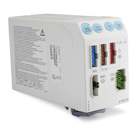
GE HEALTHCARE E-PSMP Blood Pressure Pump manual available for free PDF download: Technical Manual
GE HEALTHCARE E-PSMP Technical Manual (622 pages)
Module Frames and Modules
Brand:
GE HEALTHCARE
| Category:
Medical Equipment
| Size: 14 MB
Table of Contents
Table of Contents
13
About this Manual
7
1 Product Overview
15
Introduction
15
Measurement Principle
16
Ecg
16
Respiration
16
Invasive Blood Pressure
16
Temperature
16
Pulse Oximetry
17
Nibp
19
Main Components
20
Controls and Connectors
20
E-PSM(P) and E-(P)RE(S)TN Modules
22
ECG Board
23
STP Board
25
NIBP Board
30
2 Configuration
34
STP/TP /ST-Settings
34
3 Maintenance and Checkout
36
Replacement of Planned Maintenance Parts
36
Required Parts
36
Replacement Procedures
36
Visual Inspections
36
Electrical Safety Tests
37
Functional Check
37
Setup
37
ECG Tests
41
Impedance Respiration Tests
41
Invasive Pressure Tests
42
Temperature Tests
42
Spo2 Tests
42
NIBP Tests
43
Test Completion
44
4 Calibration and Adjustments
45
Invasive Pressure Calibration
45
Setup
45
Procedure
46
Temperature Calibration
47
Setup
47
Procedure
47
NIBP Calibration
48
Setup
49
Procedure
49
5 Troubleshooting
52
Visual Inspection
52
Troubleshooting Checklist
52
Service Interface
53
Configuration Information
53
Device Information
53
Log Files
53
Messages
54
Ecg
54
Impedance Respiration
56
Invasive Pressure
56
Temperature
58
Spo2
58
Nibp
59
Troubleshooting Chart
63
Invasive Pressure
63
Temperature
63
6 Disassembly and Reassembly
64
Disassembly Guidelines
64
ESD Precautions
64
Before Disassembly
64
Required Tools
65
Disassembling and Reassembling Procedure, E-PRESTN, E-PRETN, E-RESTN
65
Removing the Pump Unit
71
Replacing the NIBP Air Filter
72
Disassembling and Reassembling Procedure, E-PSMP and E-PSM
72
Removing the Pump Unit
76
Removing the Manifold Unit
77
Removing the Module Bus Connector
78
Replacing the NIBP Air Filter
79
7 Service Parts
80
Ordering Parts
80
E-Prestn, E-Pretn, E-Restn
81
Front Cover for E-PRESTN, E-PRETN, E-RESTN
84
Patient Side Modules, E-PSM, E-PSMP (Rev. 01)
86
Patient Side Modules, E-PSM, E-PSMP (Rev. 00)
88
Front Panel Labeling, E-PSM(P) (Rev. 00 and 01)
89
Spare Parts for PSM Mounts
90
8 Earlier Revisions
91
Maintenance Check Form
93
Table of Contents
97
1 Product Overview
99
Introduction
99
Measurement Principle
100
Principle
100
Calibration of the Pulse Contour Cardiac Output
100
Main Components
101
Controls and Connectors
101
E-Picco Module
101
Measurement Board
101
2 Configuration
105
Software Update
105
3 Maintenance and Checkout
106
Visual Inspections
106
Electrical Safety Tests
106
Functional Check
107
Test Setup
107
Invasive Pressure Tests
108
Cardiac Output Tests
108
Test Completion
109
4 Calibration and Adjustments
110
Invasive Pressure Calibration
110
Required Tools
110
Connections
110
Procedure
110
5 Troubleshooting
112
Visual Inspection
112
Troubleshooting Checklist
112
Service Interface
113
Device Information
113
Log Files
113
Messages
115
Invasive Pressure
115
Cardiac Output
116
Troubleshooting Chart
118
Invasive Pressure
118
6 Disassembly and Reassembly
119
Disassembly Guidelines
119
ESD Precautions
119
Before Disassembly
119
Required Tools
120
Disassembling and Reassembling Procedure
120
To Replace the
120
To Disassemble the Module
120
Reassembling the Module
120
7 Service Parts
121
Ordering Parts
121
Continuous Cardiac Output Module, E-Picco
121
Maintenance Check Form
123
Table of Contents
127
1 Product Overview
129
Introduction
129
Measurement Principle
130
Cardiac Output and REF
130
Svo2 Measurement
131
Invasive Blood Pressure Measurement
132
Main Components
132
Controls and Connectors
132
E-COP and E-Copsv Modules
133
Measurement Board
133
2 Configuration
138
3 Maintenance and Checkout
139
Visual Inspections
139
Electrical Safety Tests
139
Functional Check
140
Test Setup
140
Invasive Pressure Tests
141
Cardiac Output Tests
142
Svo2 Tests
142
Test Completion
143
4 Calibration and Adjustments
144
Invasive Pressure Calibration
144
Required Tools
144
Connections
144
Procedure
145
5 Troubleshooting
147
Visual Inspection
147
Troubleshooting Checklist
147
Service Interface
148
Device Information
148
Log Files
148
Messages
150
Invasive Pressure
150
Cardiac Output
151
Svo2
152
Troubleshooting Chart
152
Invasive Pressure
152
6 Disassembly and Reassembly
153
Disassembly Guidelines
153
ESD Precautions
153
Before Disassembly
153
Required Tools
154
Disassembling and Reassembling Procedure
154
To Replace the
154
To Disassemble the Module
154
Reassembling the Module
154
7 Service Parts
155
Ordering Parts
155
Cardiac Output Module, E-COP
155
Cardiac Output Module, E-Copsv
157
Maintenance Check Form
161
Table of Contents
165
1 Product Overview
167
Introduction
167
Pressure Module, E-P, Pressure Temp Module, E-PT
167
Measurement Principle
168
Invasive Blood Pressure
168
Temperature
168
Main Components
169
Controls and Connectors
170
STP Main Assembly
171
2 Configuration
175
P/PT/PP-Setting
175
3 Maintenance and Checkout
177
Visual Inspections
177
Electrical Safety Tests
177
Functional Check
178
Test Setup
178
Invasive Pressure Tests
179
Temperature Tests
179
Test Completion
180
4 Calibration and Adjustments
181
Invasive Pressure Calibration
181
Calibration Setup
181
Procedure
181
Temperature Calibration
183
Setup
183
Procedure
183
5 Troubleshooting
185
Visual Inspection
185
Troubleshooting Checklist
185
Service Interface
185
Configuration Information
185
Device Information
186
Log Files
186
Messages
186
Invasive Pressure
186
Temperature
188
Troubleshooting Chart
189
Invasive Pressure
189
Temperature
189
6 Disassembly and Reassembly
190
Disassembly Guidelines
190
ESD Precautions
190
Before Disassembly
190
Required Tools
191
Disassembling and Reassembling Procedure
191
Replacing the
191
Detaching the STP Main Assembly
191
Reassembling the Module
191
7 Service Parts
192
Ordering Parts
192
Pressure and Pressure Temp Modules E-P, E-PT, E-PP
192
The Front Covers for E-P, E-PT, E-PP
194
Table of Contents
201
1 Product Overview
203
Introduction
203
Main Components
203
Masimo Spo 2 Board (MS-2011)
204
E-MASIMO Interface Board
205
2 Configuration
207
3 Maintenance and Checkout
208
Visual Inspections
208
Electrical Safety Tests
208
Functional Check
209
Test Setup
209
Spo2 Test Procedure
209
Test Completion
209
4 Calibration and Adjustments
210
5 Troubleshooting
211
Visual Inspection
211
Troubleshooting Checklist
211
Service Interface
212
Device Information
212
Log Files
212
Messages
213
6 Disassembly and Reassembly
214
Disassembly Guidelines
214
ESD Precautions
214
Before Disassembly
214
Required Tools
215
Disassembly and Reassembly Procedure
215
To Replace the Front Cover
215
To Replace the Masimo Spo2 Board or Masimo Interface Board
215
Reassembling the Module
215
7 Service Parts
216
Ordering Parts
216
Masimo Compatible Saturation Module, E-MASIMO
216
Maintenance Check Form
219
Nellcor Compatible Saturation Module, E-Nsatx
223
1 Product Overview
225
Introduction
225
Main Components
225
E-Nsat
226
E-Nsatx
226
NIO Interface Board
227
2 Configuration
229
3 Maintenance and Checkout
230
Visual Inspections
230
Electrical Safety Tests
230
Functional Check
231
Test Setup
231
Spo2 Test Procedure
231
Test Completion
231
4 Calibration and Adjustments
232
5 Troubleshooting
233
Visual Inspection
233
Troubleshooting Checklist
233
Service Interface
234
Device Information
234
Log Files
234
Messages
235
6 Disassembly and Reassembly
237
Disassembly Guidelines
237
ESD Precautions
237
Before Disassembly
237
Required Tools
238
Disassembly and Reassembly Procedure
238
To Replace the
238
To Replace the Nellcor Pulse Oximetry Board or the NIO Interface Board
238
Reassembling the Module
238
7 Service Parts
239
Service Parts for Nellcor Compatible Saturation Module, E-NSATX
240
Oxygen Saturation Module, E-NSAT
242
Maintenance Check Form
245
Table of Contents
249
1 Product Overview
251
Introduction
251
Respiratory Modules, E-Scaiovx, E-Scaiov, E-Scaio
251
Measurement Principle
254
O2 Measurement
254
Patient Spirometry
254
Main Components
256
Controls and Connectors
257
Gas Sampling System
258
Minitpx Measuring Unit
261
Miniom Oxygen Sensor
262
Minipvx Measuring Unit
264
Gas Exchange
264
CPU Board
265
Miniom Board
265
Minipvx Board
265
Main Component Interactions
266
2 Configuration
267
Software Update
267
3 Maintenance and Checkout
268
Replacement of Planned Maintenance Parts
269
Required Parts
269
Planned Maintenance Kits
269
Replacement Procedures
269
Visual Inspections
270
Functional Check
271
Test Setup
271
Procedure
271
Test Completion
276
4 Calibration and Adjustments
277
Sample Flow Rate Adjustment
277
Calibration Setup
279
Gas Calibration
279
Procedure
280
Spirometry Calibration
282
Calibration Setup
282
Calibration Check
283
Flow Calibration
283
5 Troubleshooting
285
Visual Inspection
285
Troubleshooting Checklist
285
Gas Sampling System Troubleshooting
286
Miniom Measuring Unit Troubleshooting
286
Minitpx Measuring Unit Troubleshooting
286
Minipvx Measuring Unit Troubleshooting
286
CPU Board Troubleshooting
287
Service Interface
287
Device Information
287
Log Files
287
Messages
288
Gas Measurements
288
Spirometry
291
Gas Exchange
292
Service Gas Module Messages
293
Troubleshooting Charts
295
Patient Spirometry
295
Gas Exchange
297
6 Disassembly and Reassembly
298
Disassembly Guidelines
298
Serviceable Parts
298
Service Limitations
298
ESD Precautions
299
Protection from Dust
299
Before Disassembly
300
Required Tools
300
Disassembly and Reassembly Procedure
300
Detaching the
301
Detaching the Module Casing
302
Replacement of Planned Maintenance Parts
303
Replacement of CO
303
Absorber
303
Detaching the Latch
304
Detaching the Front Chassis Unit
305
Detaching the Main Flow Connector
306
Detaching the PVX Unit
307
Detaching the Pump
308
Detaching the OM Holder
309
7 Service Parts
310
Ordering Parts
310
Planned Maintenance Kits
310
Spare Parts
311
Front Covers
313
Maintenance Check Form
317
Table of Contents
321
1 Product Overview
323
Introduction
323
Compact Airway Modules, E-Caiovx, E-Caiov, E-Caio
323
Measurement Principle
324
Patient Spirometry
326
Gas Exchange Measurement
327
Main Components
328
Controls and Connectors
329
Gas Sampling System
330
TPX Measuring Unit
332
PVX Measuring Unit
333
CPU Board
334
OM Board
335
2 Configuration
337
3 Maintenance and Checkout
338
Replacement of Planned Maintenance Parts
338
Required Parts
338
Planned Maintenance Kits
339
Replacement Procedures
339
Visual Inspections
342
Functional Check
342
Test Setup
342
Procedure
343
Test Completion
346
4 Calibration and Adjustments
347
Sample Flow Rate Adjustment
347
Calibration Setup
347
Gas Calibration
348
Calibration Setup
349
Procedure
350
Spirometry Calibration
351
Calibration Setup
351
Calibration Check
352
Flow Calibration
352
5 Troubleshooting
354
Visual Inspection
354
Troubleshooting Checklist
354
Gas Sampling System Troubleshooting
355
OM Measuring Unit Troubleshooting
355
TPX Measuring Unit Troubleshooting
355
PVX Measuring Unit Troubleshooting
357
CPU Board Troubleshooting
357
Service Interface
357
Device Information
357
Log Files
357
Messages
358
Gas Measurements
358
Spirometry
361
Gas Exchange
362
Troubleshooting Charts
362
Patient Spirometry
363
Gas Exchange
365
6 Disassembly and Reassembly
366
Disassembly Guidelines
366
Serviceable Parts
366
Service Limitations
366
ESD Precautions
367
Protection from Dust
367
Before Disassembly
367
Required Tools
368
Disassembly and Reassembly Procedure
368
Removing the Module Casing
368
PVX Unit
368
Pump Unit
368
Tightening the Screw Inside the Sampling Pump
369
CPU Board
369
Software of CPU Board
370
7 Service Parts
371
Ordering Parts
371
Planned Maintenance Kits
371
Spare Parts for E-Caiovx, E-Caiov, E-Caio, E-COVX, E-COV, E-CO
372
D-FEND Latch
377
Maintenance Check Form
378
Table of Contents
383
1 Product Overview
385
Introduction
385
Measurement Principle
385
CO2 Measurement
385
Main Components
387
Controls and Connectors
387
Gas Sampling System
387
Minic Sensor
390
CPU Board
390
2 Configuration
391
3 Maintenance and Checkout
392
Replacement of Planned Maintenance Parts
392
Required Parts
392
Replacement Procedures
393
Visual Inspections
394
Functional Checkout
394
Test Setup
394
Procedure
395
Test Completion
396
4 Calibration and Adjustments
398
Sample Flow Rate Adjustment
398
Calibration Setup
398
Gas Calibration
399
Calibration Setup
400
Procedure
401
5 Troubleshooting
403
Visual Inspection
403
Troubleshooting Checklist
403
Gas Sampling System Troubleshooting
404
Minic Sensor Troubleshooting
404
Service Interface
404
Device Information
404
Log Files
405
Messages
406
Troubleshooting Chart
408
6 Disassembly and Reassembly
411
Disassembly Guidelines
411
Serviceable Parts
411
Service Limitations
411
ESD Precautions
411
Protection from Dust
412
Before Disassembly
412
Required Tools
412
Disassembling and Reassembling Procedure
413
Removing the Module Casing
413
Replacing the Pump Unit
413
Replacing the Minico2 Assembly
414
7 Service Parts
415
Ordering Parts
415
Single-Width Airway Module, E-Minic
415
Maintenance Check Form
418
Table of Contents
421
1 Product Overview
423
Introduction
423
Measurement Principle
424
Entreeg
424
Femg
424
RE and SE
424
Impedance Measurement
425
Main Components
425
Controls and Connectors
425
Entropy Board
426
2 Configuration
427
3 Maintenance and Checkout
428
Visual Inspections
428
Electrical Safety Tests
428
Functional Check
429
Test Setup
429
Entropy Tests
429
Test Completion
429
4 Calibration and Adjustments
430
5 Troubleshooting
431
Visual Inspection
431
Troubleshooting Checklist
431
Service Interface
432
Device Information
432
Log Files
432
Messages
433
Troubleshooting Chart
435
6 Disassembly and Reassembly
436
Disassembly Guidelines
436
ESD Precautions
436
Before Disassembly
436
Required Tools
437
Disassembling and Reassembling Procedure
437
Reassembling the Module
437
7 Service Parts
438
Ordering Parts
438
Table of Contents
445
1 Product Overview
447
Introduction
447
Measurement Principle
447
Eeg
447
Femg
448
Aep
448
Impedance Measurement
448
Main Components
449
Controls and Connectors
449
2 Configuration
452
3 Maintenance and Checkout
453
Visual Inspections
453
Electrical Safety Tests
454
Functional Check
454
Test Setup
454
EEG Tests
454
Test Completion
455
4 Calibration and Adjustments
456
5 Troubleshooting
457
Visual Inspection
457
Troubleshooting Checklist
458
Service Interface
458
Device Information
458
Log Files
458
Messages
459
6 Disassembly and Reassembly
461
Disassembly Guidelines
461
ESD Precautions
461
Before Disassembly
461
Required Tools
462
Disassembly and Reassembly Procedure
462
E-Eeg
462
N-Eeg
462
7 Service Parts
464
Ordering Parts
464
EEG Module, E-EEG
464
Table of Contents
473
1 Product Overview
475
Introduction
475
Accessories
475
Measurement Principle
476
BIS Measurement on the Monitor Screen
476
Sensor Check
476
Main Components
477
Controls and Connectors
477
BIS Measurement System Block Diagram
478
Bisx Digital Signal Processing Unit
478
BIS Module
479
2 Configuration
480
3 Maintenance and Checkout
481
Visual Inspections
481
Electrical Safety Tests
482
Functional Check
482
Test Setup
482
BIS Tests
482
Test Completion
482
4 Calibration and Adjustments
483
5 Troubleshooting
484
Visual Inspection
484
Troubleshooting Checklist
484
Service Interface
485
Device Information
485
Log Files
485
Messages
486
Troubleshooting Chart
487
6 Disassembly and Reassembly
488
Disassembly Guidelines
488
ESD Precautions
488
Before Disassembly
488
Required Tools
489
Disassembly and Reassembly Procedure
489
Replacing the
489
Replacing the Interface Board
489
Reassembling the Module
489
7 Service Parts
490
Table of Contents
497
1 Product Overview
499
Introduction
499
Measurement Principle
500
Nerve Stimulation
500
Tetanic/Ptc
500
Response Measurement
501
EMG Measurement
501
Mechanosensor Measurement
501
Regional Block
501
Main Components
502
Controls and Connectors
502
NMT Board
502
Stimulator
503
2 Configuration
504
3 Maintenance and Checkout
505
Visual Inspections
505
Electrical Safety Tests
505
Functional Check
506
Test Setup
506
NMT Tests
506
Test Completion
507
4 Calibration and Adjustments
508
5 Troubleshooting
509
Visual Inspection
509
Troubleshooting Checklist
509
Service Interface
510
Device Information
510
Log Files
510
Messages
511
6 Disassembly and Reassembly
513
Disassembly Guidelines
513
ESD Precautions
513
Before Disassembly
513
Required Tools
514
Disassembly and Reassembly Procedure
514
Replacing the
514
Replacing the NMT Board
514
Reassembling the Module
514
Table of Contents
523
1 Product Overview
525
Introduction
525
Functional Description
525
Main Components
527
Connectors and Signals
527
EMBC Board
530
Power Board
530
Mother Board
531
PDM/PSM Flex Board
531
Front Panel Flex Board
531
2 Configuration
532
3 Maintenance and Checkout
533
Visual Inspections
533
Electrical Safety Tests
534
Functional Check
534
Test Setup
534
Module Communication Test
534
Synchronization Connector Test
535
Test Completion
537
4 Calibration and Adjustments
538
5 Troubleshooting
539
Visual Inspection
539
LED Indicators
539
Troubleshooting Checklist
540
Service Interface
541
Configuration Information
541
Device Information
541
Log Files and Snapshots
541
Messages
542
Troubleshooting Chart
542
F5 and F7 Module Frames
542
6 Disassembling and Reassembling
544
Disassembly Guidelines
544
ESD Precautions
544
Before Disassembly
544
Disassembly and Reassembly Procedure
545
7-Module Frame, F7
545
5-Module Frame, F5
548
Table of Contents
563
1 Product Overview
565
Introduction
565
Measurement Principle
565
Main Components
566
Internal Main Components
566
Battery
567
PDM Eport Host Interface Cable
568
Controls
568
Connectors
569
Hardware Installation
569
PDM Admit/Discharge Cycle
572
2 Configuration
573
Webmin Login
573
Asset Settings
574
Licensing
575
ECG Filter Configuration
576
Software Update
576
3 Maintenance and Checkout
577
Visual Inspection
577
Electrical Safety Tests
577
Checkout Procedure
577
Test Setup
577
ECG Tests
581
Impedance Respiration Tests
582
Invasive Pressure Tests
582
Temperature Tests
582
Spo2 Tests
582
NIBP Tests
584
Defib/Sync and Analog Output Test
585
Test Completion
587
Complete Checkout Form
587
Battery Care
587
Use Recommendations
588
Storage Recommendations
588
Test the Battery Charge
588
Charge the Battery
588
Condition the Battery
589
4 Calibration and Adjustments
590
Nibp
590
Required Equipment
590
Calibration Check Procedure
590
Calibration Procedure
591
Analog Outputs
592
Required Equipment
592
Test Cable Plug and Pinout
593
Procedure
593
5 Troubleshooting
596
Before You Begin
596
Device Information and Diagnostics
596
Device Information
596
Diagnostics
596
Problems and Solutions
597
Error Messages
599
6 Disassembly and Reassembly
601
Disassembly Guidelines
601
Before Disassembly
601
Hardware Precautions
601
Electrostatic Discharge (ESD) Precautions
601
Exploded View
602
Replacement Procedures
603
Labels
604
Battery Door and Tray
605
Pull Tab and Mount Rail
605
Top Housing
607
Main Board
609
NIBP Hose and Coupling
610
NIBP Assembly with Manifold Hose
611
Main Flex Circuit Assembly
612
Recommended Checkout
616
7 Service Parts
618
Ordering Parts
618
Parts
618
Maintenance Check Form
619
Advertisement
Advertisement
Related Products
GE HEALTHCARE Ettan DALTsix
GE HEALTHCARE E-PSM
GE HEALTHCARE E-PRESTN
GE HEALTHCARE E-RESTN
GE HEALTHCARE E-PRETN
GE HEALTHCARE B20
GE HEALTHCARE B40
GE HEALTHCARE CARESCAPE Monitor B450
GE HEALTHCARE CARESCAPE Monitor B650
GE HEALTHCARE Logiq Book XP series
GE HEALTHCARE Categories
Medical Equipment
Laboratory Equipment
Fitness Equipment
Measuring Instruments
Control Unit
More GE HEALTHCARE Manuals
Login
Sign In
OR
Sign in with Facebook
Sign in with Google
Upload manual
Upload from disk
Upload from URL