Sign In
Upload
Manuals
Brands
GE Manuals
Toy
DC EVOLUTION Series
GE DC EVOLUTION Series Manuals
Manuals and User Guides for GE DC EVOLUTION Series. We have
1
GE DC EVOLUTION Series manual available for free PDF download: Operating Manual
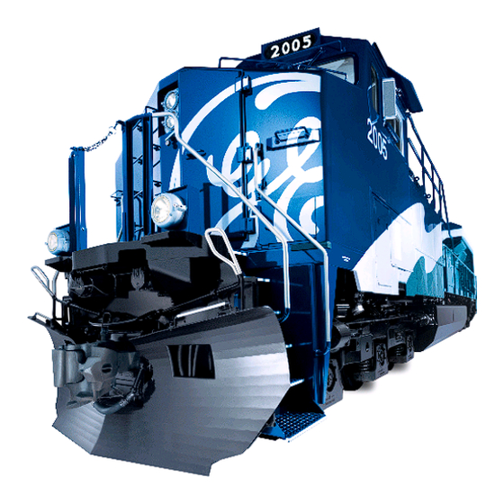
GE DC EVOLUTION Series Operating Manual (149 pages)
DIESEL–ELECTRIC LOCOMOTIVE
Brand:
GE
| Category:
Toy
| Size: 4 MB
Table of Contents
Table of Contents
3
Summary of Warnings and Cautions
8
Proposition 65 Warning
8
Introduction
12
Acronyms and Abbreviations
12
Consolidated Control Architecture
13
Smart Displays (Sdis)
13
CCA System Block Diagram
14
SDIS Keyboard (Typical)
15
Consolidated Input/Output Cio Panel
16
Engine Control Unit
16
Main Operation Screen
16
Dynamic Brake Operation
17
Electronic Air Brake System (Eab)
17
Event Recorder System
17
End-Of-Train System
18
Global Positioning Satellite (Gps) System
18
Auto Engine Start/Stop (Aess) System
18
Location of Apparatus
20
DC Evolution Series Location of Apparatus
20
General Data
22
Operating Equipment
24
Introduction
24
Devices in Nose/Operating Cab
24
Two-Way Radio
25
Smart Display
25
Control Stand Devices
25
Operator Control Console, Top
25
Mechanical Interlocking
26
Master Controller Handle Positions
26
Smart Display Operation Screen
29
Sample Operation Screen Informational Areas
30
Control Console Bottom Devices
33
Operator Control Console, Bottom
34
Engine Control Panel Devices
35
Engine Control Panel
36
Engine Control Switch
37
Devices on the Overhead Console
38
Devices in Crew Member's Area
39
Overhead Control Console
39
Horn Pushbutton
40
Crew Member's Console
40
Air Brake Equipment
42
Electronic Air Brake System
42
Electronic Air Brake Controller (EBV)
43
Air Brake Equipment in Air Brake Compartment
44
Air Brake Compartment Equipment Location
45
Cut-Out Cocks
46
Sand Control Valves and Piping
46
Air Brake End Connections
46
Electro-Pneumatic Control Unit (EPCU) Component Location
47
Other Equipment
48
Electronic Equipment Alcove
48
Electronic Equipment Locker
49
Other Operator Cab Features
50
Control Compartment Equipment
50
Blowers and Fans
50
Typical Toilet Compartment
51
Overhead Dome Light and Wiper Controls
52
Operator/Crew Member's Overhead Speaker
52
Location of Control Areas
53
Air Compressor
54
Location of Equipment, Dynamic Braking, Exhauster and Alternator Blowers, Air-To-Air and Radiator Fan
54
Air Compressor Control Panel (CCP) and Piping
55
Miscellaneous Equipment
56
Other Gages
56
Draining Cooling Water System
56
Side of Fuel Tank Showing Cut-Off, Fill, and Gauge
56
Cooling-Water Fill Box
57
Winter Operation
59
Maintenance Battery Switch (Mbs)
59
Safeguards, Alerts and Shutdowns
62
Alerter
62
Alarm Bell
62
Barring-Over Switch
62
Engine Air Filter Pressure Sensor (Eafp)
62
Engine Stop and Emergency Fuel Cut-Off System
62
Ground Cut-Out Switch
63
Motor and Speed Sensor Cut-Out Switch Functions
65
Dynamic Brake Cut-Out Switch Function
65
Locked Axle Cut-Out Switch Function
66
Oil and Water Temperature and Pressure
66
Overspeed - Engine Shutdown
66
Overspeed - Locomotive
67
Pcs Function Operation
67
Wheelslip
67
Sanding
68
Operator Message Screen
68
Operator Messages
69
Operation
70
On Power-Up
70
Locomotive Operating Display
70
Preparation for Operation
79
Before Boarding Locomotive
79
After Boarding Locomotive
79
Starting Engine
80
Cold Weather Engine Starting/Warm-Up
82
Charging a Train
82
Before Moving Locomotive
82
Moving a Train
83
Stopping a Train
84
Reversing Locomotive
84
Stopping Engine
84
Before Leaving Locomotive
85
Safety Controls
85
Dynamic Brake Operation
85
Operating as a Leading Unit
86
Operating as a Trailing Unit
87
Changing Operating Ends
87
To Operate with Other Types of Units
87
Dead Heading (Dead-In-Train)
88
Electric Parking Brake Control Panel and Manual Override
88
Locomotive Operation by Sdis Screen
92
Electronic Air Brake
94
Introduction
94
Current Status
94
Operation
95
Electronic Air Brake Set-Up, Lead
96
Electronic Air Brake Set-Up, Trail
96
Air Brake Troubleshooting
97
Reset Strategy
97
Reset Strategies
97
End of Train
100
Introduction
100
Operation
101
Operating Procedure
102
Distributed Power System Operation Summary
106
Introduction
106
Operation
106
Operating Procedure
107
Slow Speed While Distributed Power Active
112
Slow Speed Control
114
Introduction
114
Operation
115
Power Reduction
118
Plug Loading
120
Switches
122
Introduction
122
Operation
122
Dynamic Brake Cut-Out Switch Function
124
Locked Axle Cut-Out Switch Function
124
Distance Counter
126
Introduction
126
Operation
126
Measured Mile
130
Introduction
130
Operation
130
Auto Engine Start/Stop (Aess)
132
Introduction
132
Operation
134
Screen Controls
138
Introduction
138
Operation
139
Operator Password
140
Data Download
142
Introduction
142
Operation
142
Trip Monitor
144
Introduction
144
Operation
145
Locomotive Monitor
146
Introduction
146
Operation
146
Advertisement
Advertisement
Related Products
GE DASH 8 IFC
GE DCVH680
GE DCVH680GJWW
GE DCVH480EKWW
GE DCVH660EHMS - G.E. 7.0 Cu.Ft. Electric Dryer
GE DCVH680EJMR - 7.0 cu.ft. Electric Dryer
GE DCB330 and
GE DCVH680EJ0MV
GE DCLR333H
GE DCLR333GT
GE Categories
Refrigerator
Ranges
Microwave Oven
Dishwasher
Air Conditioner
More GE Manuals
Login
Sign In
OR
Sign in with Facebook
Sign in with Google
Upload manual
Upload from disk
Upload from URL