Sign In
Upload
Manuals
Brands
GC5 Manuals
I/O Systems
iSMA-B-W0202
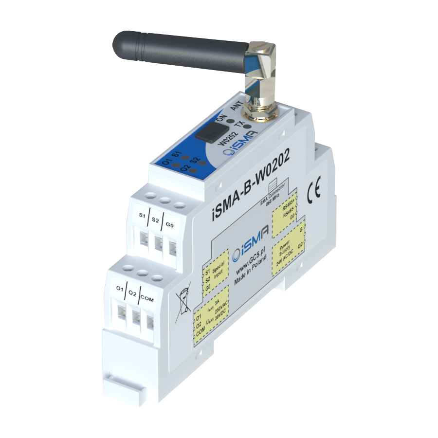
GC5 iSMA-B-W0202 I/O Module Manuals
Manuals and User Guides for GC5 iSMA-B-W0202 I/O Module. We have
1
GC5 iSMA-B-W0202 I/O Module manual available for free PDF download: User Manual
GC5 iSMA-B-W0202 User Manual (43 pages)
Modbus
Brand:
GC5
| Category:
I/O Systems
| Size: 1 MB
Table of Contents
Table of Contents
2
Introduction
4
Revision History
4
Safety Rules
5
Technical Specifications
6
Dimension
7
Power Supply Connection
7
1.5.1 DC Power Connection
7
1.5.2 AC Power Connection
7
Connecting the Communication Bus
8
LED Indication
8
Grounding and Shielding
9
RS485 Network Termination
9
Module Configuration
9
Communication
10
Special Inputs
10
Digital Outputs
11
Radio Settings
11
Radio Status
12
Configuration Registers
13
Firmware Version and Module Type (30001)
13
Counter of Received Messages (30004)
13
Counter of Error Messages (30006)
13
Counter of Sent Messages (30008)
13
Up Time (30012)
13
Device Actions (40001)
14
Modbus Protocol Type (40134)
14
Modbus Address (40135)
14
Baud Rate (40136)
14
Stop Bits (40137)
15
Data Bits (40138)
15
Parity Bit (40139)
15
Response Delay Time (40140)
15
Watchdog Time (40141)
16
Watchdog for Radio
16
Radio Configuration Registers
16
Radio TX Power (40242)
16
Radio Channel (40243)
16
Radio Baud Rate (40244)
18
Radio AESKEY (40249 - 40256)
19
Radio Received Frames Counter (40257)
19
Radio ERROR Frames Counter (40259)
19
Radio Transmitted Frames Counter (40261)
19
Wireless Device Status (40263 - 40390)
20
Special Inputs Connections
21
Connection of Special Input to Measure Voltage 0 - 10 V
21
Connection of Special Input to Measure Temperature
21
Connection of Special Input as a Digital Input (Dry Contact)
21
Special Inputs MODBUS Registers
22
Status of Special Inputs Working as Digital Inputs (30017)
22
Special Input Measure Voltage 1 - 2 (30071, 30073)
22
Special Input Measure Temperature 1 - 2 (30072, 30074)
22
Special Input Measure Resistance 1 - 2 (30103-30104, 30105-30106)
22
Fast Counter (40023-40024, 40025-40026)
23
Resetting Counters Values (40022)
23
Special Input Configuration 1 - 2 (40151 - 40152)
24
Filter Time of the Special Input 1 - 2 (40159 - 40160)
24
Digital Outputs (Relays) Connections
25
Connecting a Solenoid Valve to the Digital Output
25
Connecting a Resistive Load to the Digital Output
25
Digital Outputs (Relays) MODBUS Registers
26
State of Digital Outputs (40018)
26
Default State of Digital Outputs (40143)
26
Special Application Modes
27
Operation Mode Registers (40176,40180)
28
8.1.1 Ordinary IO
28
8.1.2 Monostable Relay
28
8.1.3 Bistable Relay
28
Time Relay no [Ms]
28
Time Relay NC [Ms]
29
Time Relay no [S]
29
Time Relay NC [S]
29
8.1.8 Input Forwarding
29
8.1.9 Heating Mode
30
8.1.10 Cooling Mode
31
Command Register (40020)
32
Block Inputs Register (40021)
32
Setpoint Registers (40178,40182)
32
Differential Registers (40179,40183)
32
List of Modbus Registers
33
List of Supported Temperature Sensors
38
Advertisement
Advertisement
Related Products
GC5 iSMA MINI Series
GC5 iSMA MIX Series
GC5 Categories
I/O Systems
Control Unit
Control Panel
More GC5 Manuals
Login
Sign In
OR
Sign in with Facebook
Sign in with Google
Upload manual
Upload from disk
Upload from URL